AI Generated Quiz
Secondary 4 Pure Physics Electricity Magnetism Quiz
Free Sec 4 Pure Physics Electricity Magnetism quiz, Kimi2.6 AI version, with questions, answers, and O Level-style practice for Singapore students.
These static practice materials are generated from the site's syllabus and paper-generation workflow, with source and model context shown so students and parents can evaluate the material before use.
Questions
Free quiz and exam paper access
Enter your details to view this paper
Your access is remembered on this device.
Answers
Secondary 4 Pure Physics Quiz - Electricity Magnetism: Answer Key
Total Marks: 40
Section A: Multiple Choice and Short Answer
[Total: 20 marks]
1. Georg Simon Ohm (or "Ohm") [1]
Teaching note: The unit of resistance, the ohm (Ω), is named after the German physicist who established the fundamental relationship between voltage, current, and resistance.
2. Resistance calculation [2]
Working: Using Ohm's Law:
Ω [1 for formula, 1 for answer with unit]
Answer: 20 Ω
Teaching note: Ohm's Law states that for a conductor at constant temperature, the current is directly proportional to the potential difference. The resistance is the ratio .
3. An ohmic conductor obeys Ohm's Law (current proportional to voltage, constant resistance), while a non-ohmic conductor does not obey Ohm's Law (resistance changes with voltage/current). [1]
Alternative answer: An ohmic conductor has constant resistance regardless of voltage/current; a non-ohmic conductor has resistance that varies with temperature or applied voltage.
4. Parallel resistors calculation [3]
Working: For parallel resistors:
Ω [1]
Using Ohm's Law: A [1 for calculation, 1 for answer with unit]
Alternative method: Current through each resistor = A, so total current = A
Answer: 6.0 A
Teaching note: In parallel, the reciprocal of total resistance equals the sum of reciprocals. Alternatively, calculate current through each branch and add (same method, more intuitive).
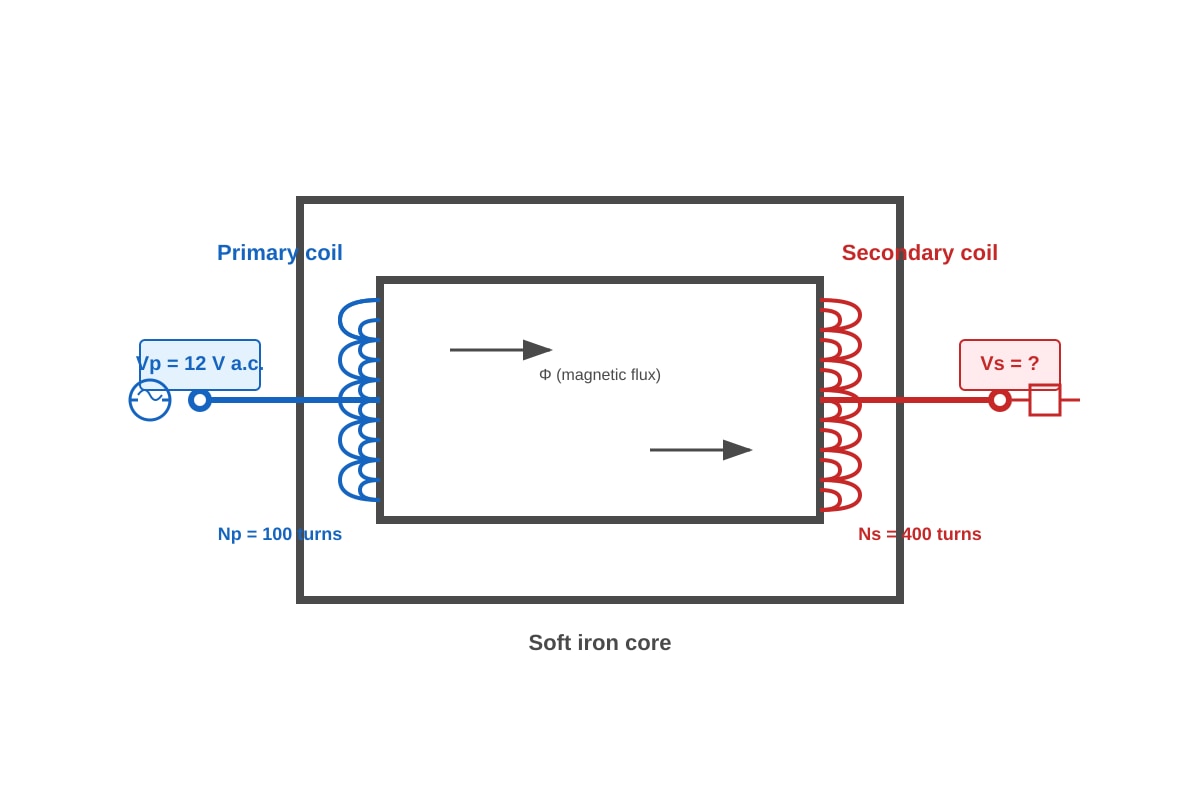
5. Transformer question [3 total]
(a) Step-up transformer. [1] The secondary coil has more turns (400) than the primary coil (100), which increases the voltage. [1]
(b) Using the transformer equation:
V [1 for formula, 1 for answer with unit]
Answer: 48 V
Teaching note: A step-up transformer increases voltage by having more turns on the secondary. The voltage ratio equals the turns ratio. This uses alternating current; transformers do not work with d.c.
6. Fuse explanation [2]
When too many appliances operate simultaneously, the total current drawn exceeds the fuse rating. [1] The fuse wire heats up due to its resistance, melts when the current exceeds its rating, and breaks the circuit, preventing overheating of cables and potential fire. [1]
Teaching note: Power . More appliances mean more total power, hence more current at fixed voltage. The fuse is a safety device that sacrifices itself to protect the circuit.
7. Kettle calculations [5 total]
(a) , so A (or 8.7 A) [1 for formula, 1 for answer]
(b) Energy = Power × time = 2000 × (5.0 × 60) = 2000 × 300 = 600 000 J [1 for conversion, 1 for formula, 1 for answer with unit]
Or: Energy = 000 J
Answers: (a) 8.7 A (accept 8.70 A); (b) 600 000 J or J
Teaching note: Time must be in seconds for energy calculations. 5.0 minutes = 300 s. The kettle's high power explains why kettles need thick cables and appropriate fuses.
8. Safety features in three-pin plug [4]
Any two from:
| Feature | Purpose |
|---|---|
| Fuse | Melts and breaks circuit if current exceeds safe value, preventing fire [2 marks: 1 for feature, 1 for purpose] |
| Earth wire | Provides safe path for current if live wire touches metal casing, preventing electrocution [2 marks] |
| Insulated casing/plastic | Prevents user from touching conducting parts [2 marks] |
| Cable grip | Secures cable to prevent strain on internal connections [2 marks] |
Teaching note: The earth wire is connected to the metal casing of Class I appliances. If the live wire frays and touches the casing, current flows to earth rather than through a person.
9. Factors affecting solenoid magnetic field strength [2]
Any two from:
- Number of turns per unit length (more turns = stronger field) [1]
- Magnitude of current (larger current = stronger field) [1]
- Presence of soft iron core (greatly increases field strength) [1]
10. Force direction using Fleming's left-hand rule [2]
Direction: Upwards (or "out of page/up") [1]
Explanation using Fleming's left-hand rule: First finger points in direction of magnetic field (N to S, left to right), second finger points in direction of current (into page), thumb points in direction of force (upwards). [1]
Teaching note: For conventional current (positive to negative), use left hand. The force is perpendicular to both field and current. The ⊗ symbol means current going into the page (arrow moving away).
Section B: Structured Response
[Total: 12 marks]
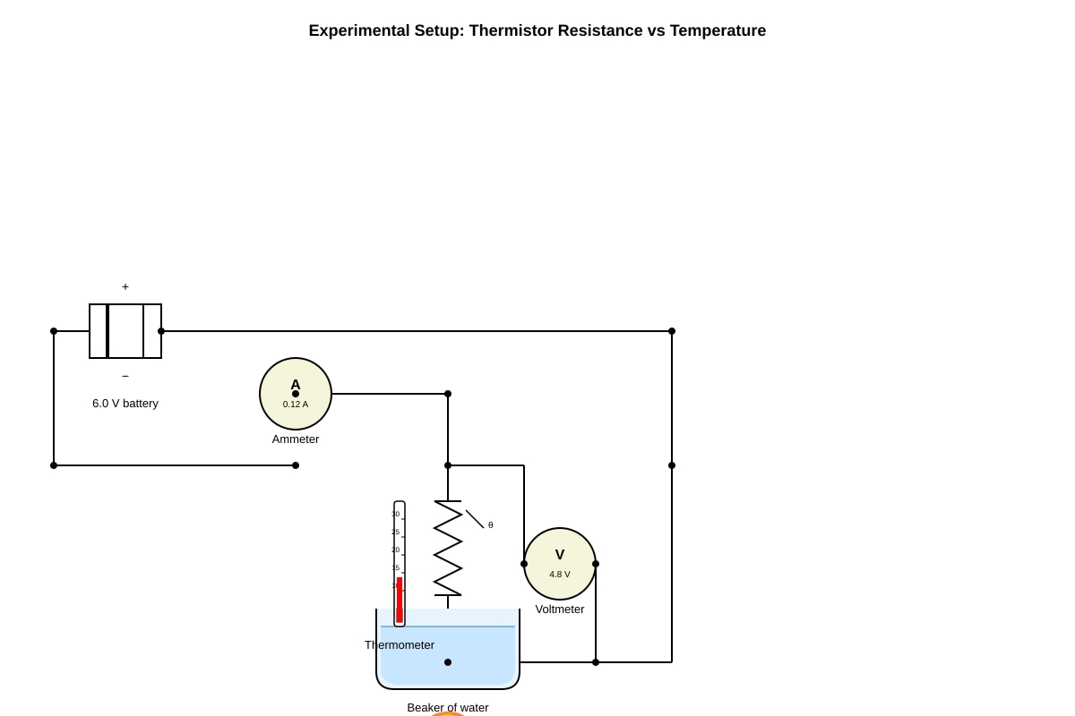
11. Thermistor experiment [5 total]
(a) Submerging in water ensures even heating of the thermistor and allows accurate temperature measurement with the thermometer. [1] Direct heating would causeuneven temperature distribution and possible damage. [1] Accept: water bath provides controlled, uniform temperature.
(b) Ω [1 for formula, 1 for answer with unit] [2]
(c) In a thermistor (semiconductor), increasing temperature releases more charge carriers (electrons) from the crystal lattice. [1] More charge carriers available for conduction means lower resistance and higher current for the same voltage. [1]
Teaching note: This is opposite to metallic conductors where resistance increases with temperature. In semiconductors, thermal energy frees electrons from bonds, increasing carrier density dramatically.
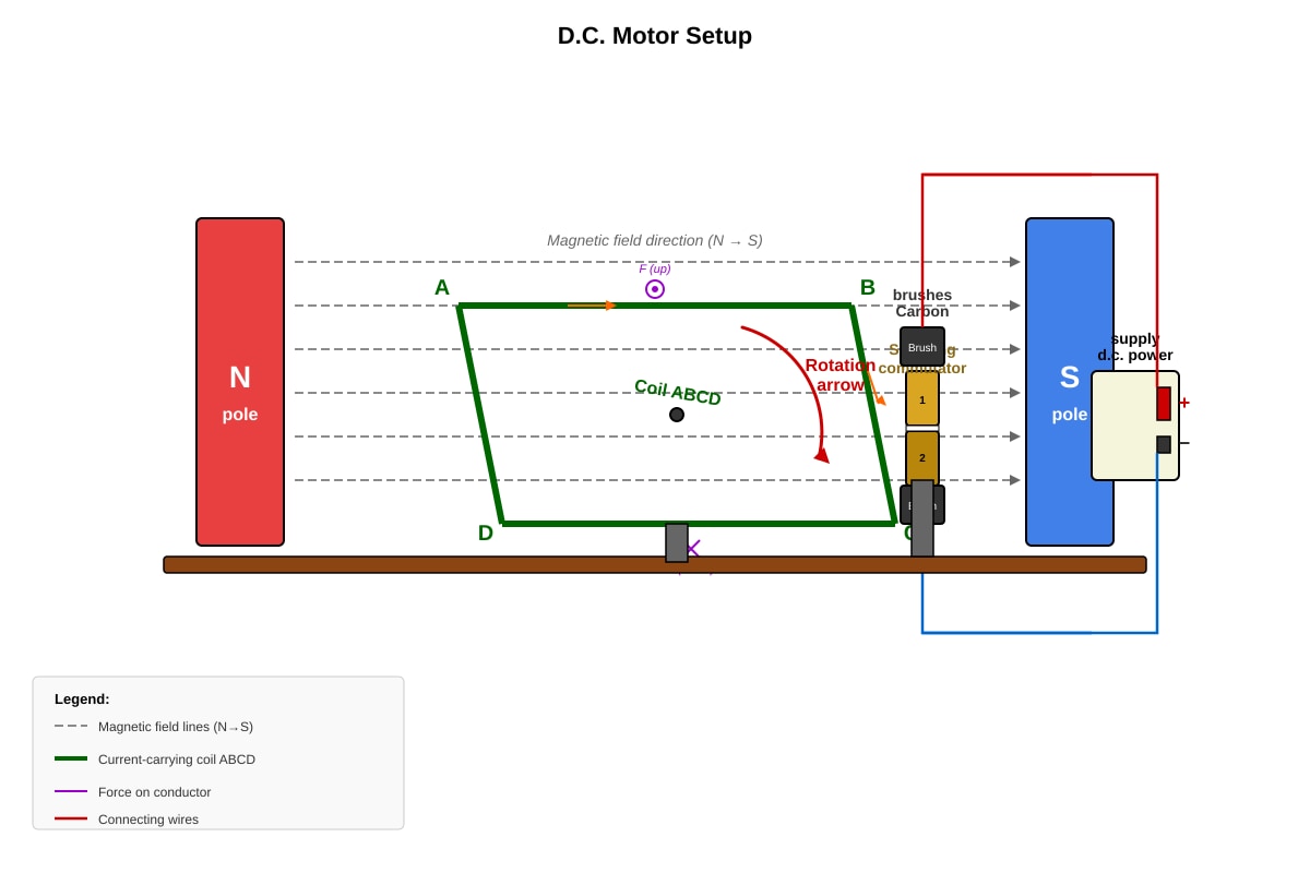
12. D.C. motor [4 total]
(a) Current flows through the coil in a magnetic field. [1] By Fleming's left-hand rule, one side of the coil experiences force upwards, the other side experiences force downwards, creating a couple/torque that causes rotation. [1] The split-ring commutator reverses current every half turn to maintain rotation in one direction. [1] (Any 2 points for 2 marks)
(b) Any two from:
- Increase the current through the coil [1]
- Increase the strength of the magnetic field (stronger magnets/more turns) [1]
- Increase the number of turns on the coil [1]
- Insert a soft iron core in the coil [1]
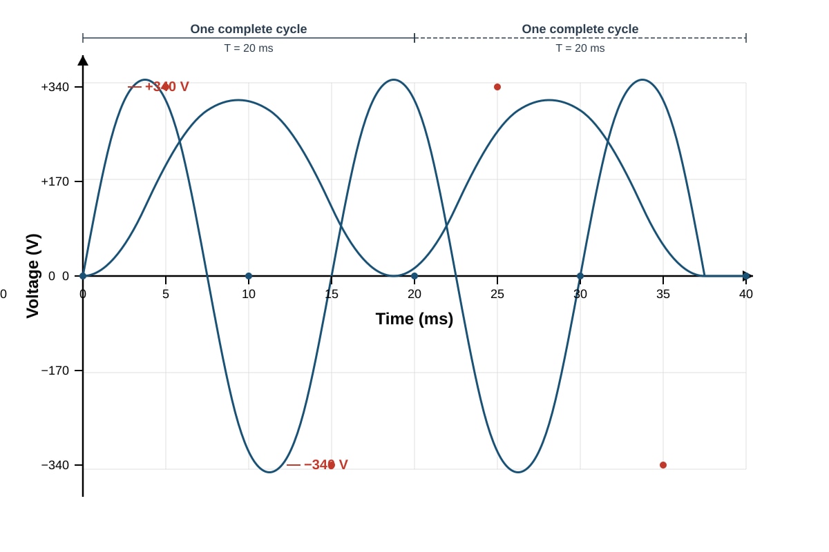
13. A.C. generator [3 total]
(a) V [1 for formula, 1 for calculation, 1 for answer] [2]
Accept 240 V or 241 V.
(b) The r.m.s. value represents the equivalent d.c. voltage that would deliver the same power to a resistive load. [1] It allows direct comparison of heating effect and power transfer between a.c. and d.c. supplies. [1]
Teaching note: 240 V is standard mains voltage in Singapore/UK. The peak is about 340 V. The √2 factor comes from averaging the squared sine wave over a cycle.
14. Transformer calculations [5 total]
(a)
turns [1 for formula, 1 for answer]
(b)
A [1 for efficiency formula, 1 for substitution, 1 for answer]
Answers: (a) 60 turns; (b) 0.13 A (accept 0.130 A)
Teaching note: For efficiency, output power is always less than input power. Don't forget to convert 80% to 0.80 in calculations. Real transformers have energy losses due to eddy currents, hysteresis, and copper resistance.
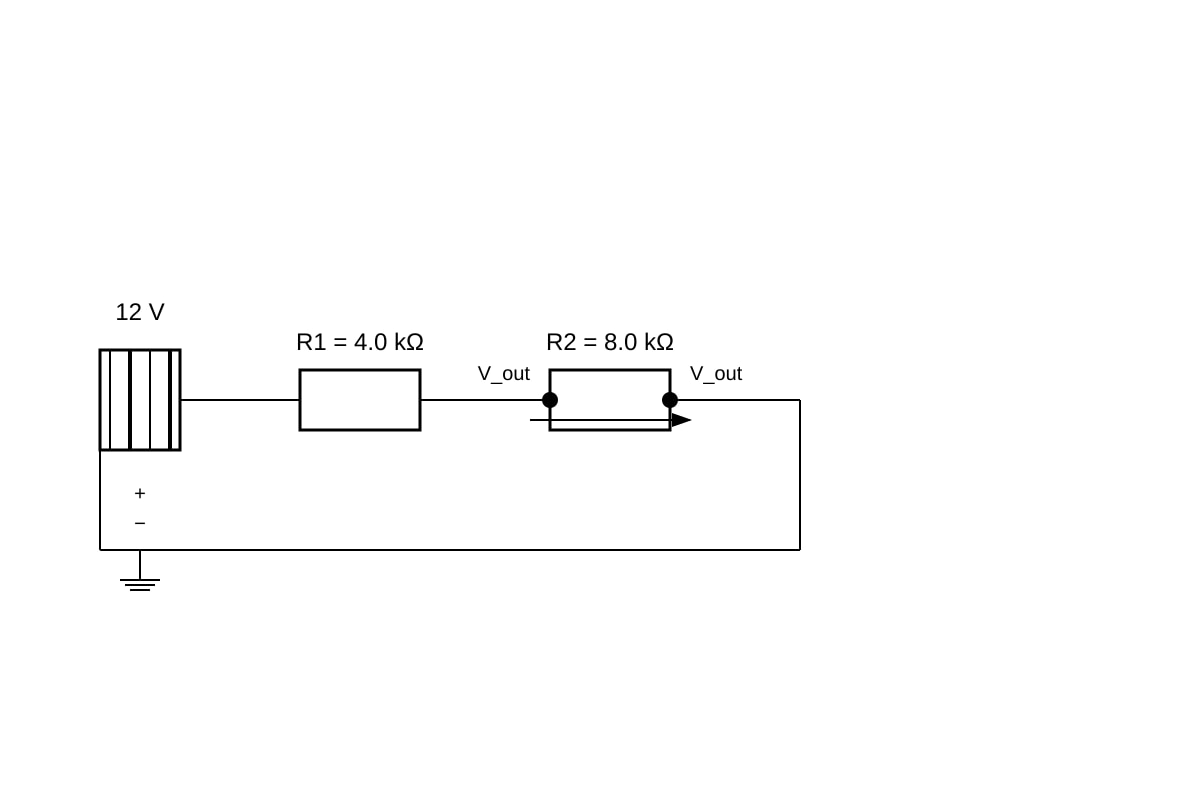
15. Potential divider [4 total]
(a) Using potential divider formula: V [1 for formula, 1 for answer]
Alternatively: Total current A; V
(b) The output voltage decreases. [1] Adding a 4.0 kΩ resistor in parallel with R2 reduces the effective resistance of the lower part of the divider. [1] The parallel combination: , so kΩ. [1] Since this is less than the original 8.0 kΩ, the output voltage falls.
Teaching note: The potential divider splits voltage in proportion to resistances. Loading the output (adding a parallel resistor) changes the division ratio. This is why voltage followers (high input impedance) are used in electronics.
Section C: Extended Response
[Total: 8 marks]
16. High voltage transmission [2]
Power loss in cables is , where is the resistance of the transmission cables. [1] To transmit the same power (), using higher voltage means lower current, which dramatically reduces heat losses in the cables. [1] This improves efficiency and allows thinner, cheaper cables to be used.
17. Electromagnetic induction experiment [3]
Apparatus: Bar magnet, coil of wire, galvanometer (sensitive ammeter) or center-zero microammeter. [1]
Procedure: Move the magnet into the coil. Observe deflection on galvanometer. Move magnet out of coil; observe opposite deflection. [1]
Direction dependence: When the N pole enters, current flows one direction; when N pole exits, current reverses. [1] Or: entering vs exiting produces opposite deflections; inverting the magnet (S pole first) reverses the deflection again.
Alternative: Use two coils (primary and secondary) with changing current in primary.
Teaching note: Faraday's Law states that induced e.m.f. is proportional to rate of change of magnetic flux linkage. Lenz's Law gives the direction: the induced current opposes the change causing it.
18. Lightning conductor [2]
The lightning conductor is a metal rod with a pointed tip at the top of the building, connected by a thick copper strip to a metal plate buried in the earth. [1] When a charged cloud approaches, the sharp point creates a strong electric field that ionizes air molecules, allowing charge to leak to the atmosphere gradually (corona discharge), preventing sudden discharge. [1] If lightning does strike, the low-resistance path safely conducts the enormous current to earth, preventing damage to the building.
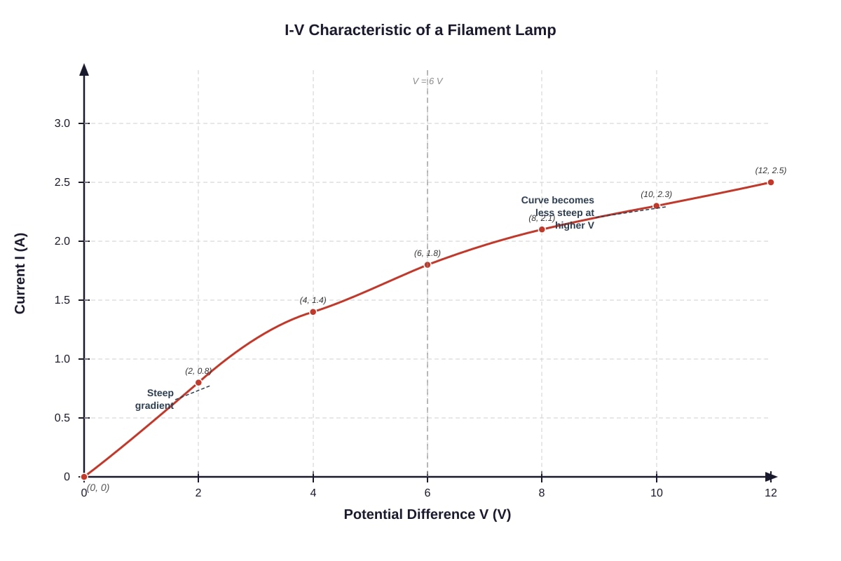
19. Filament lamp resistance [3]
As voltage increases, current increases, and the filament temperature rises significantly. [1] Lattice ions in the metal filament vibrate more vigorously at higher temperatures. [1] This increases collisions between conduction electrons and lattice ions, impeding electron flow. [1] Therefore resistance increases, shown by the decreasing gradient (I/V ratio falls) on the graph.
Teaching note: The I-V curve becoming less steep means resistance is increasing (as , or use from gradients). For metals, resistance increases with temperature; this is why filaments glow white-hot.
20. Circuit breaker vs fuse evaluation [3]
Advantage of circuit breaker: Can be reset after tripping, more convenient; responds faster to some faults; can detect earth leakage (RCCB/RCD). [1]
Disadvantage of circuit breaker: More expensive to install initially; more complex mechanism can fail. [1]
Advantage of fuse: Simple, cheap, reliable; fails-safe (destroys itself to break circuit). [1]
Evaluation: The claim is too absolute. For domestic situations, circuit breakers offer convenience and additional protection types, but fuses remain appropriate for simple, cost-sensitive applications or where absolute simplicity is valued. [1] The best choice depends on application, cost, and required protection features.
(Any valid advantage/disadvantage pair with balanced evaluation for full marks)
END OF ANSWER KEY