From Real Exams Quiz
Secondary 4 Pure Physics Electricity Magnetism Quiz
Free Sec 4 Pure Physics Electricity Magnetism quiz, Kimi2.6 Exam version, with questions, answers, and O Level-style practice for Singapore students.
These static practice materials are generated from the site's syllabus and paper-generation workflow, with source and model context shown so students and parents can evaluate the material before use.
Questions
Free quiz and exam paper access
Enter your details to view this paper
Your access is remembered on this device.
Answers
Secondary 4 Pure Physics Quiz - Electricity Magnetism
ANSWER KEY
Question 1 (2 marks)
Answer: B — Flow of positive charge from positive to negative terminal
Explanation: Conventional current is defined as the flow of positive charge from the higher potential (positive terminal) to the lower potential (negative terminal). This convention was established before the discovery of electrons.
Common mistake: Option A describes electron flow (actual charge carriers in metals), which is opposite in direction to conventional current. Students often confuse electron flow with conventional current direction.
Question 2 (2 marks)
Answer: C — 960 V
Working: For an ideal transformer:
Explanation: This is a step-up transformer because , so . The voltage is stepped up by the same ratio as the turns ratio.
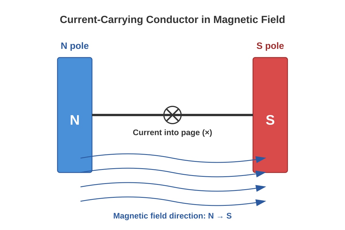
Question 3 (2 marks)
Answer: B — Vertically downward
Working: Use Fleming's Left-Hand Rule:
- First finger (Forefinger): Magnetic Field — North to South (left to right, horizontally)
- Second finger: Current — into page (marked ×)
- Thumb: Force/Motion — vertically downward
Explanation: The motor effect force direction is determined by Fleming's Left-Hand Rule. With magnetic field horizontal (N→S) and current going into the page, the thumb points downward.
Visual check from Q3-fig1: The diagram shows N pole left, S pole right, current into page (×), so force must be perpendicular to both field and current, pointing downward.
Question 4 (2 marks)
Answer: A —
Working: For resistors in parallel:
Explanation: Parallel connection provides additional pathways for current, reducing total resistance. For n identical resistors in parallel, .
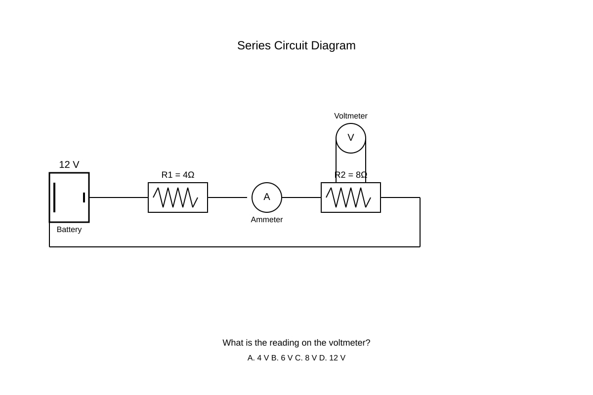
Question 5 (2 marks)
Answer: C — 8 V
Working: Total resistance: Ω
Circuit current: A
Voltage across R₂: V
Explanation: In a series circuit, current is the same throughout. Using the potential divider principle: V.
The larger resistor gets the larger share of the voltage in a series circuit.
Question 6 (3 marks)
(a) (1 mark)
Answer: (Ohm's Law) — potential difference equals current multiplied by resistance.
(b) (2 marks)
Working:
Mark scheme:
- Formula: or equivalent (1 mark)
- Correct answer with unit: 4.0 A (1 mark)
Question 7 (5 marks)
(a)(i) (1 mark)
Answer: The galvanometer needle deflects momentarily in one direction (e.g., to the right).
Explanation: Changing magnetic flux through the solenoid induces an e.m.f. (Faraday's Law). The moving magnet changes the magnetic field through the coil.
(a)(ii) (1 mark)
Answer: The needle shows zero deflection / returns to zero.
Explanation: No change in magnetic flux when the magnet is stationary. Induced e.m.f. requires a changing flux, not a steady field.
(a)(iii) (1 mark)
Answer: The needle deflects momentarily in the opposite direction (e.g., to the left).
Explanation: The magnetic flux is decreasing in the same direction (or increasing in opposite sense), and by Lenz's Law, the induced current opposes this change, reversing the direction.
(b) (2 marks) — any two from:
- Move the magnet faster — greater rate of change of flux
- Use a stronger magnet — greater flux density, so greater change in flux
- Increase number of turns on the solenoid — more conductors cutting flux
- Use a solenoid with smaller cross-sectional area / insert iron core — increases flux linkage
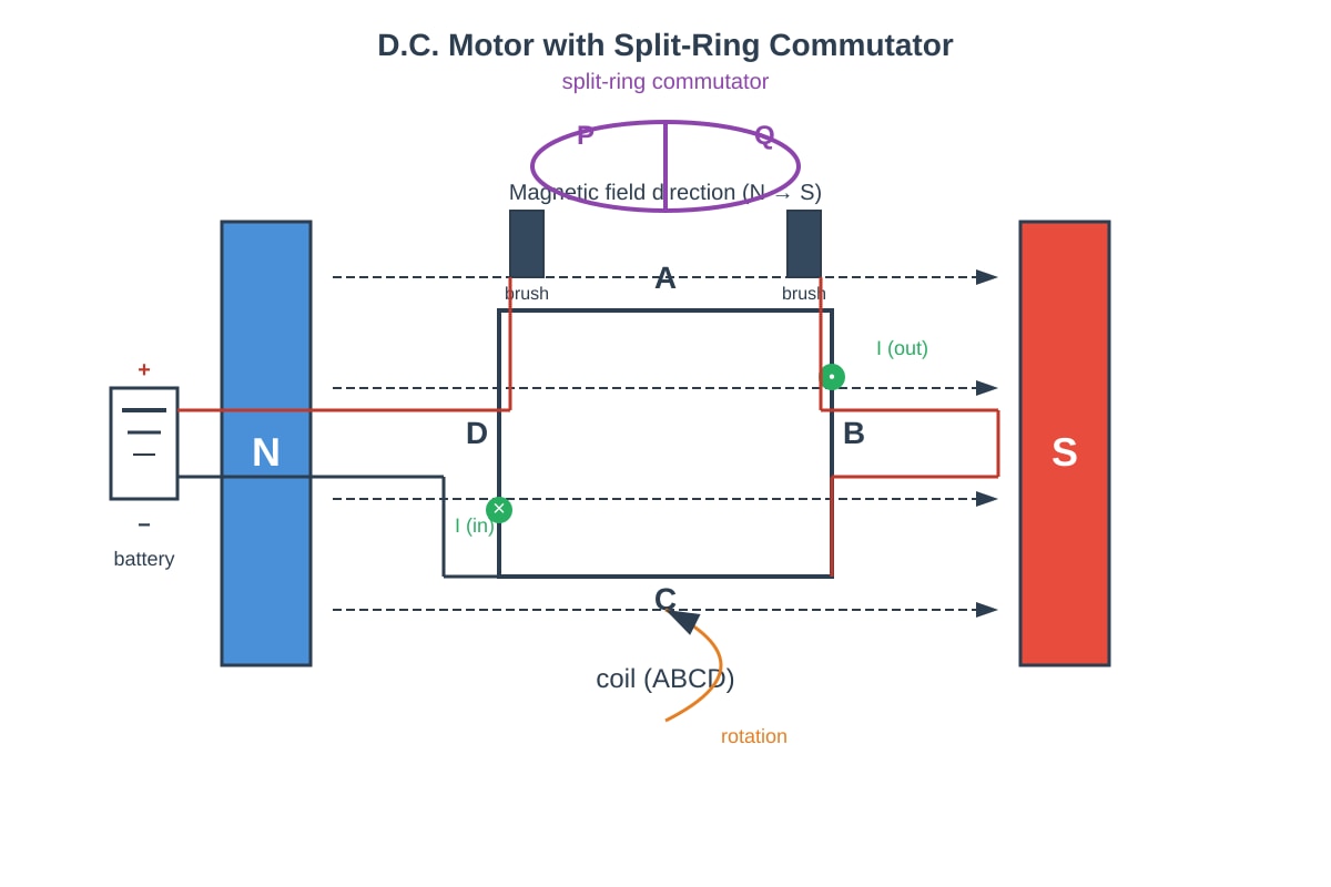
Question 8 (4 marks)
(a) (2 marks)
Answer:
- Each half of the split-ring commutator reverses the current direction in the coil every half-rotation.
- This ensures the current in the side of the coil near each magnetic pole reverses at the correct moment, so the force on each side always produces rotation in the same direction.
Marking points:
- Reverses current every half rotation (1 mark)
- Maintains continuous rotation in same direction / torque always in same direction (1 mark)
(b) (2 marks) — any two from:
- Increase the current through the coil
- Use a stronger magnetic field (stronger magnets)
- Increase number of turns on the coil
- Increase the area of the coil
Question 9 (4 marks)
(a) (2 marks)
Working:
Mark scheme:
- Formula: (1 mark)
- Answer: 8.33 A or 8.3 A (1 mark)
(b) (2 marks)
Working: Time = 5 minutes = h = h ≈ 0.0833 h
Or: kWh ≈ 0.167 kWh or 0.17 kWh
Mark scheme:
- Correct time conversion or working (1 mark)
- Correct answer with unit: 0.167 kWh or kWh or 0.17 kWh (1 mark)
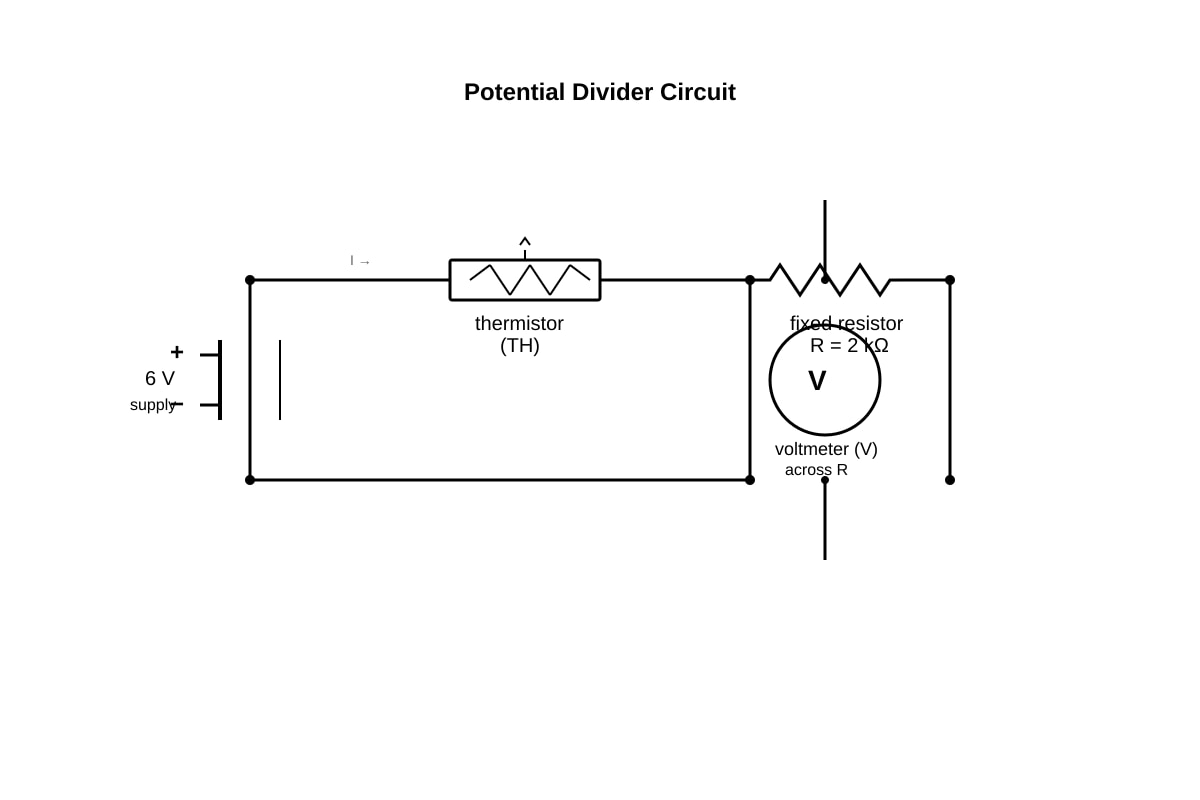
Question 10 (5 marks)
(a) (3 marks)
Working: Total resistance = kΩ = 6000 Ω
Using potential divider:
Or using current: A = 1.0 mA
Mark scheme:
- Total resistance = 6 kΩ or 6000 Ω (1 mark)
- Correct method (potential divider or current method) (1 mark)
- Correct answer: 2.0 V (1 mark)
(b) (2 marks)
Answer: The potential difference across the fixed resistor increases.
Explanation: As temperature increases, the resistance of the thermistor decreases. With lower thermistor resistance, a smaller share of the 6 V appears across it, so a larger share appears across the fixed resistor (or: total resistance decreases, current increases, so across fixed resistor increases).
Mark scheme:
- States "increases" (1 mark)
- Correct explanation linking decreased thermistor resistance to increased V across R (1 mark)
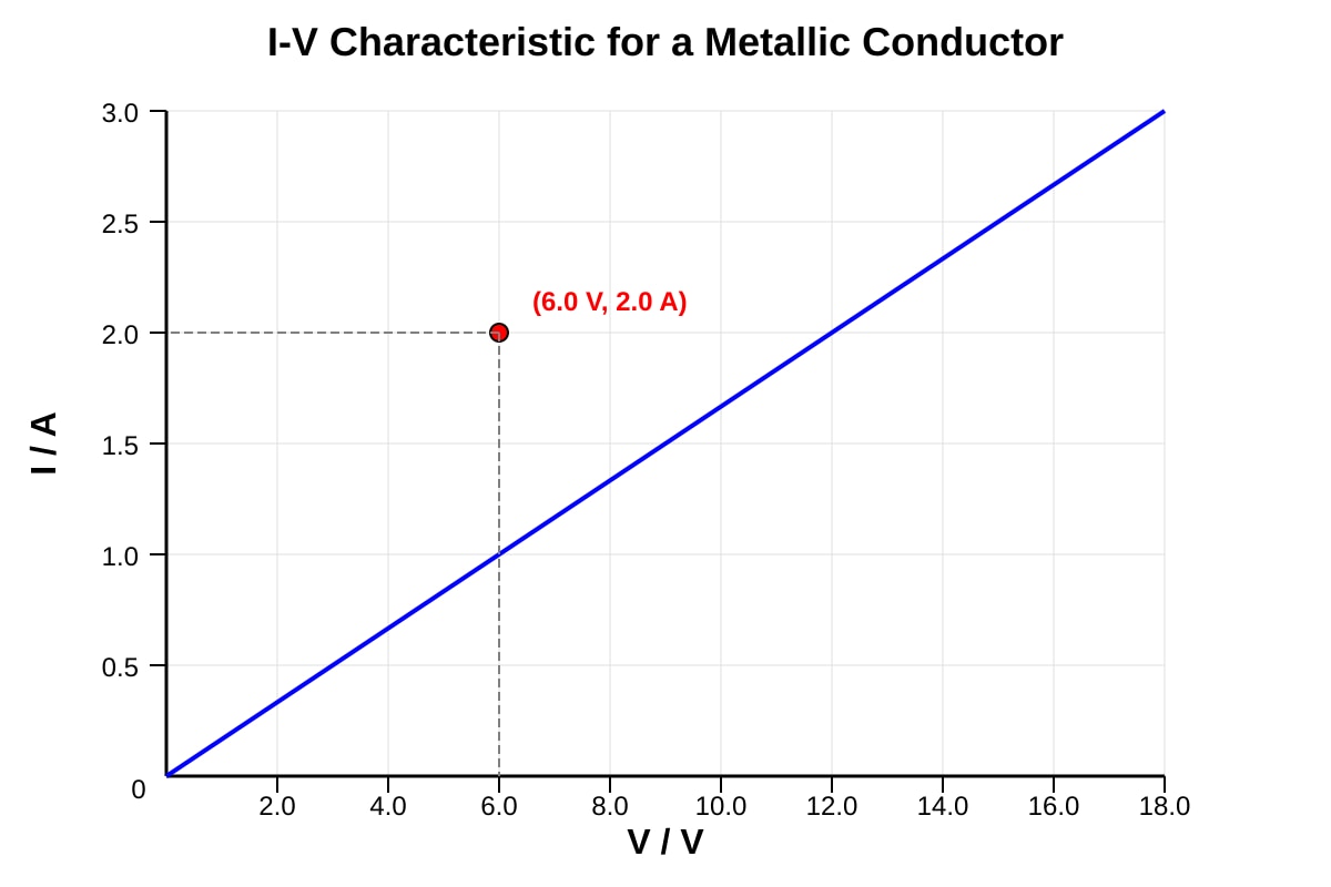
Question 11 (4 marks)
(a) (1 mark)
Answer: or conductance or
Note: The gradient of an I-V graph equals . The reciprocal of the gradient gives resistance.
(b) (2 marks)
Working: Gradient = A/V ≈ 0.333 A/V
Or read any point: Ω
Mark scheme:
- Use of or reciprocal of gradient (1 mark)
- Answer: 3.0 Ω (1 mark)
(c) (1 mark)
Answer: When V = 0, no potential difference exists to drive current, so I = 0.
Or: No electric field, so no force on charge carriers, hence no drift velocity, hence no current.
Question 12 (5 marks)
(a) (2 marks)
Working:
Mark scheme:
- Formula or ratio method (1 mark)
- Answer: 40 turns (1 mark)
(b) (3 marks)
Working: Current in each lamp: A
For 4 identical lamps in parallel: A
Or: Total power = W
Mark scheme:
- Current per lamp = 2.0 A or total power = 96 W (1 mark)
- Method for combining currents in parallel (1 mark)
- Answer: 8.0 A (1 mark)
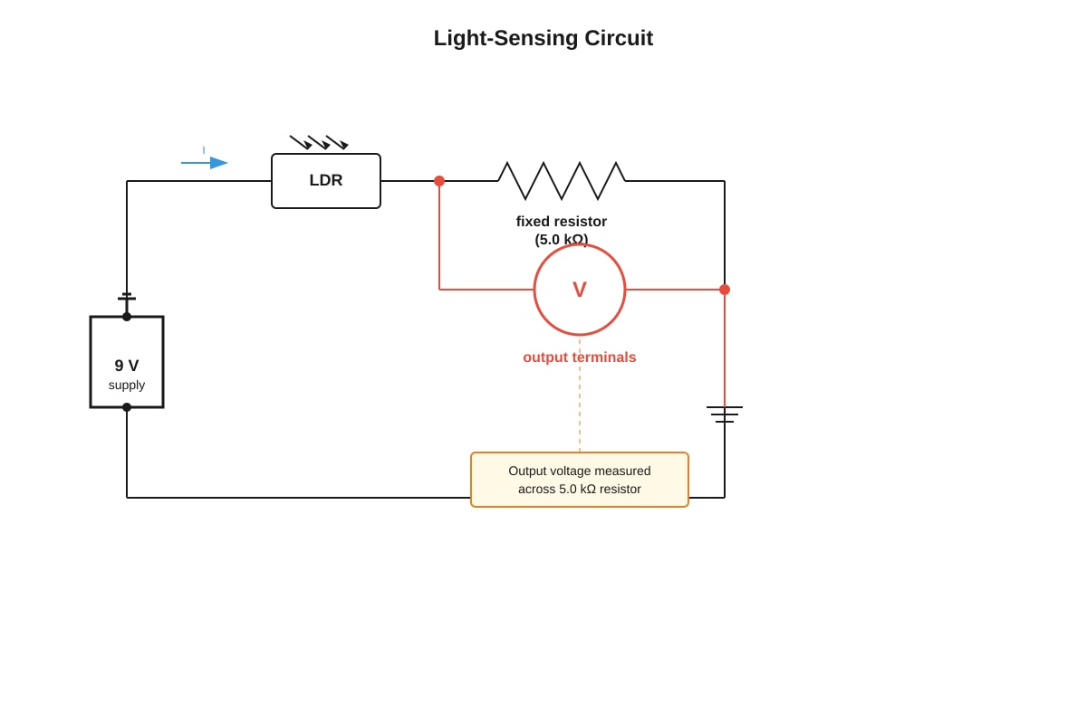
Question 13 (6 marks)
(a) (1 mark)
Answer: As light intensity increases, the resistance of the LDR decreases. (Inverse relationship / non-linear inverse relationship.)
(b) (3 marks)
Working: At 30 lux, kΩ = 2000 Ω
Total resistance = Ω
Or ≈ 6.4 V or 6.43 V
Mark scheme:
- Correct LDR resistance from table (2.0 kΩ) (1 mark)
- Potential divider method or current method (1 mark)
- Answer: 6.43 V or 6.4 V (1 mark)
(c) (2 marks)
Answer: At night, light intensity is low, so LDR resistance is high. This means the output voltage across the fixed resistor is low. This low voltage can be used to trigger a transistor or switching circuit to turn on the lamp. (Or converse: by day, high light intensity gives low LDR resistance, high output voltage, which keeps lamp off.)
Mark scheme:
- Links low light to high LDR resistance (1 mark)
- Explains how this changes output voltage to switch circuit on/off (1 mark)
Question 14 (5 marks)
(a) (2 marks)
Working: Maximum flux when coil is perpendicular to field (θ = 0°, cos θ = 1):
Or: Wb
Mark scheme:
- Correct area calculation (0.0024 m²) or formula (1 mark)
- Correct answer with unit: Wb or 0.0096 Wb (1 mark)
(b) (3 marks)
Answer:
- As the coil rotates, the angle between the coil's normal and the magnetic field changes continuously.
- This means the magnetic flux linking the coil changes with time.
- By Faraday's Law, an e.m.f. is induced when there is a change in magnetic flux linkage.
- Since the rotation is continuous, the flux alternately increases and decreases, inducing an e.m.f. that reverses direction — hence alternating e.m.f.
Mark scheme:
- Flux linkage changes as angle changes (1 mark)
- Faraday's Law: changing flux induces e.m.f. (1 mark)
- Direction reverses due to continuous rotation / alternating nature explained (1 mark)
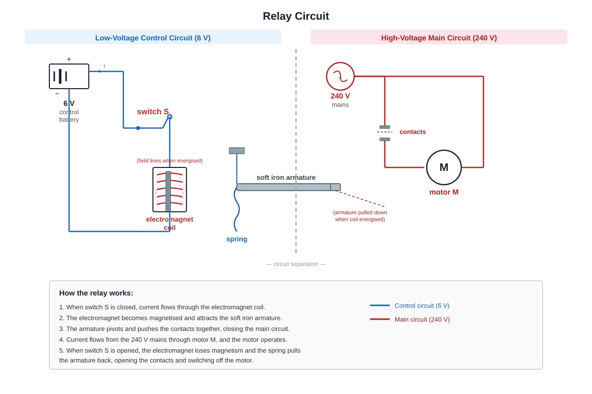
Question 15 (5 marks)
(a) (3 marks)
Answer:
- Closing switch S allows current to flow through the electromagnet coil in the control circuit.
- The electromagnet becomes magnetized and attracts the soft iron armature.
- The armature moves, closing the contacts in the high-voltage circuit.
- Current now flows through the main circuit, and motor M operates.
Mark scheme:
- Current flows, electromagnet energized/becomes magnetized (1 mark)
- Armature attracted/moves, contacts close (1 mark)
- Main circuit completed, motor operates (1 mark)
(b) (2 marks) — any two from:
- Electrical isolation: The control circuit and high-voltage circuit are electrically separate, protecting the operator from high voltage.
- Safety: Low-voltage circuits are safer to operate and can use thin, inexpensive wiring.
- Remote control: Allows switching of dangerous/high-power equipment from a safe distance or using automated systems.
- Switching high current: The low-voltage circuit doesn't need to carry the high current required by the motor.
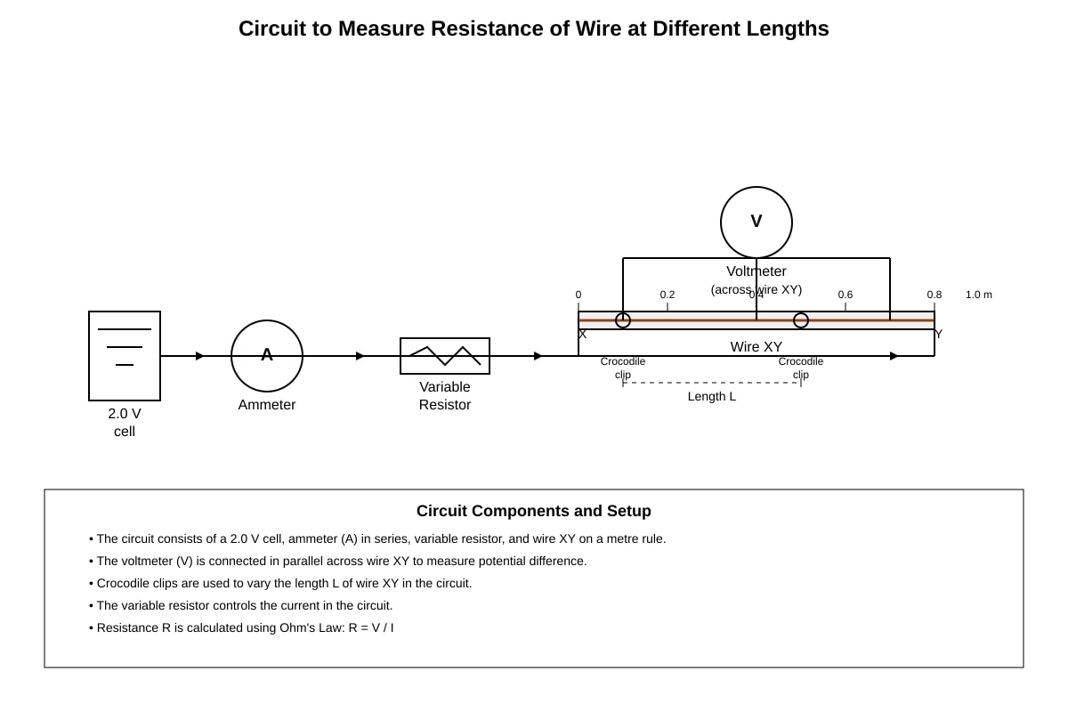
Question 16 (7 marks)
(a) (2 marks)
Answer:
- Independent variable: Length L of the wire (1 mark)
- Dependent variable: Resistance R of the wire (1 mark)
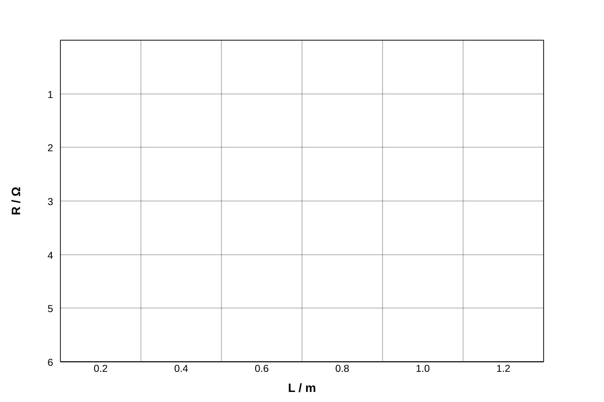
(b) (3 marks)
Marking guidance for graph (Q16-fig2):
- Correct axes labels with units: R/Ω and L/m (1 mark)
- All five points plotted accurately within ±1 mm (1 mark)
- Straight line of best fit through origin (1 mark)
(c) (2 marks)
Working: Gradient = Ω/m
Or using any two points: Ω/m
Resistance per metre = 6.0 Ω/m
Mark scheme:
- Method: gradient calculation or use of two points (1 mark)
- Answer: 6.0 Ω/m or 6 Ω/m (1 mark)
Question 17 (7 marks)
(a) (2 marks)
Working:
Mark scheme:
- Formula: (1 mark)
- Answer: 35.4 A or 35.42 A (1 mark)
(b) (3 marks)
Working: Power loss in cable:
Or using rounded value: W ≈ 500 W
Accept 500–502 W
Mark scheme:
- Use of or equivalent (1 mark)
- Correct substitution (1 mark)
- Answer: approximately 500 W or 502 W (1 mark)
(c) (2 marks)
Answer:
- High current flows in high-power appliances.
- Higher cable resistance leads to greater power loss (), wasting energy as heat in the cable.
- Also, the cable could overheat, creating a fire risk.
- Low resistance cable minimizes energy loss and keeps the cable temperature safe.
Mark scheme:
- Power loss proportional to R (or stated) (1 mark)
- Energy wasted as heat / overheating risk explained (1 mark)
Question 18 (7 marks)
(a) (2 marks)
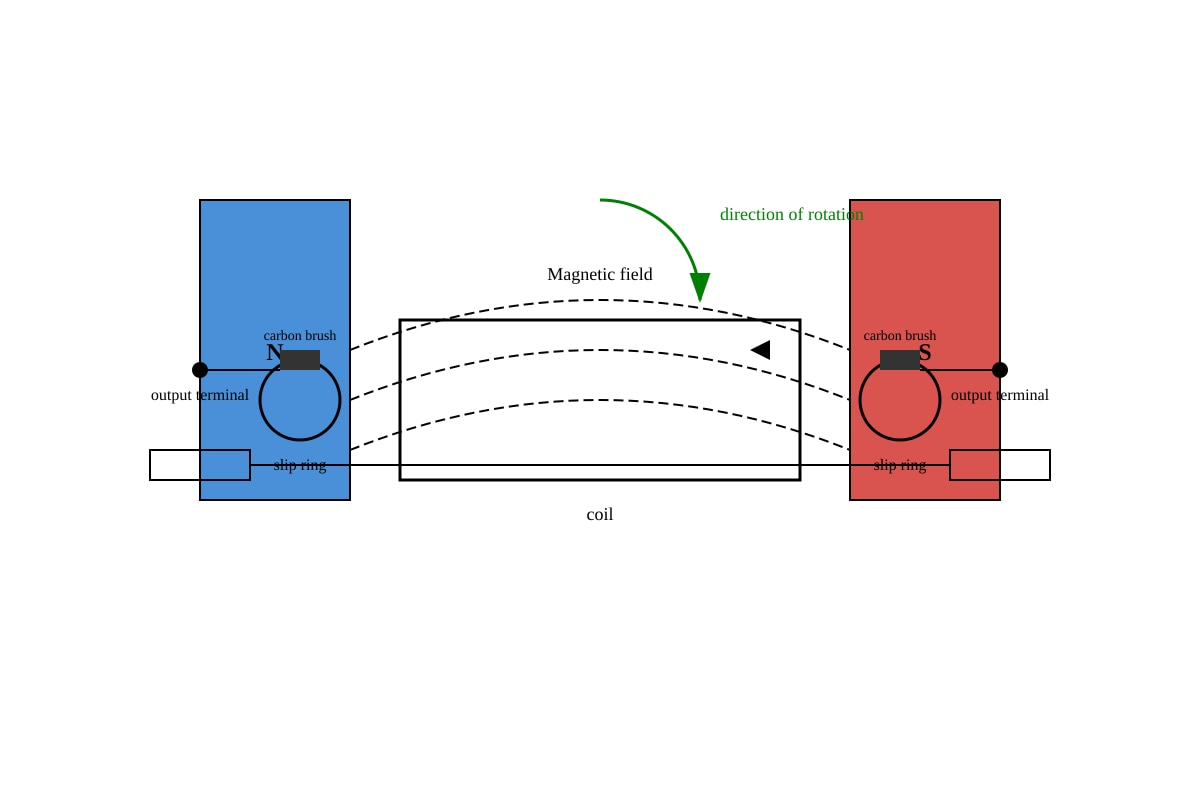
Answer:
- Slip rings provide continuous electrical connection between the rotating coil and the external circuit without reversing current direction.
- Unlike the split-ring commutator in a d.c. motor, slip rings maintain the same connection to each side of the coil, allowing the natural alternating output to be collected.
Mark scheme:
- Maintain continuous contact with rotating coil (1 mark)
- Do not reverse current / allow alternating output to be transmitted (1 mark)
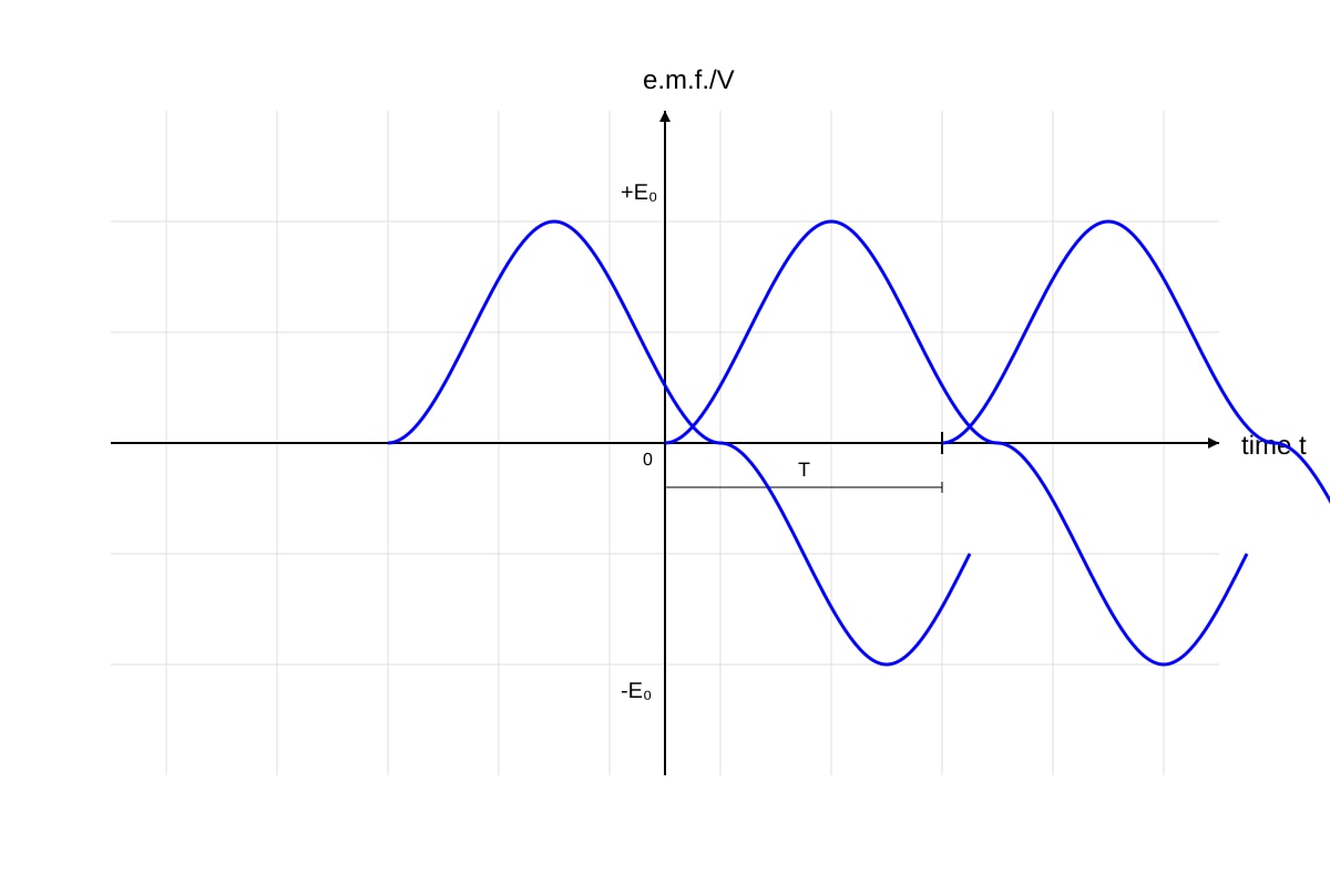
(b) (3 marks)
Expected sketch features (Q18-fig2):
- Sinusoidal wave shape centered on zero (1 mark)
- Two complete cycles shown (1 mark)
- Labels for peak value and period (1 mark)
(c) (2 marks) — any two from:
- Speed of rotation (angular velocity ω) — faster rotation gives greater rate of change of flux
- Number of turns on the coil (N) — more turns means more flux linkage
- Magnetic flux density (B) — stronger field gives greater flux
- Area of the coil (A) — larger area means more flux linkage
Question 19 (5 marks)
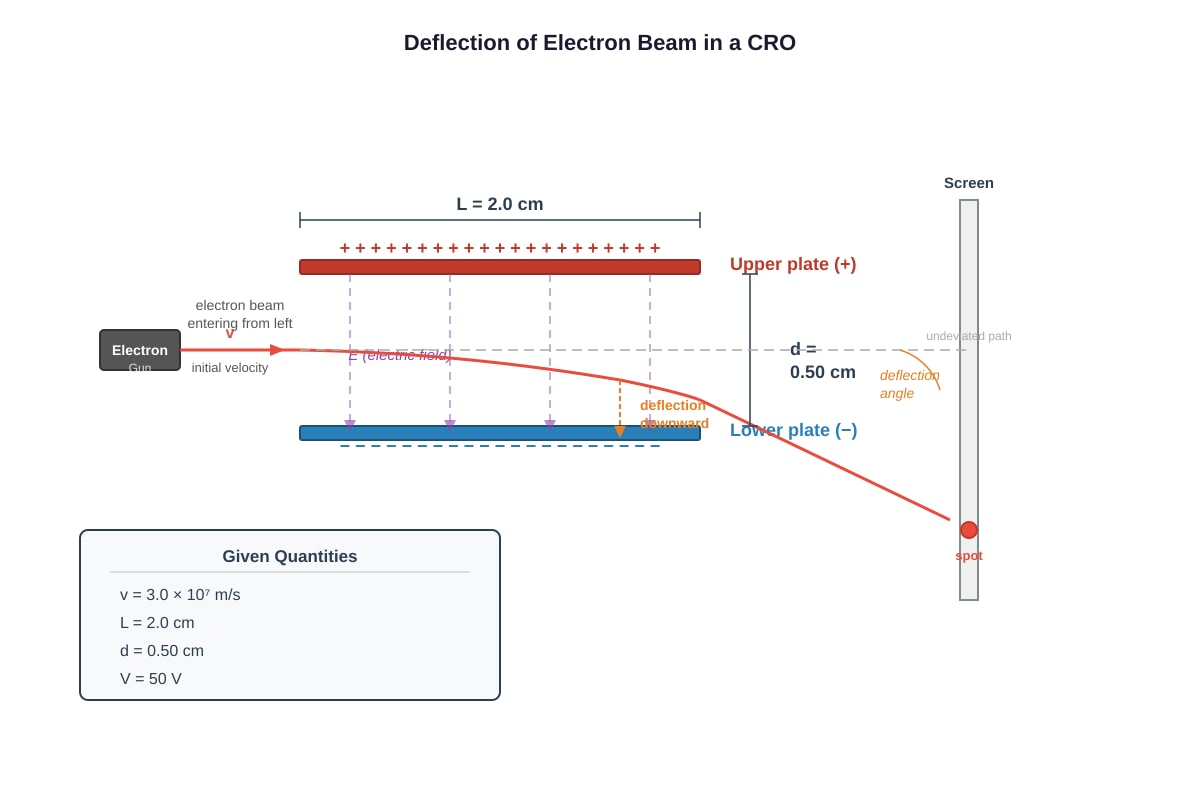
(a) (1 mark)
Answer: Electrons would collide with air molecules, scattering the beam and preventing it from reaching the screen with sufficient energy.
Or: To prevent electrons from being absorbed or scattered by air, which would defocus the beam.
(b) (2 marks)
Working:
Mark scheme:
- Formula: or substitution (1 mark)
- Answer with unit: J (1 mark)
(c) (2 marks)
Working:
Or 10 000 N/C or 10 kV/m
Mark scheme:
- Formula: with d in metres (1 mark)
- Answer: V/m or 10 000 V/m (1 mark)
Question 20 (6 marks)
(a) (3 marks)
Expected answer for Q20-fig1 sketch:
- Field lines emerge from one end of solenoid and enter the other (1 mark)
- Closed loops with lines continuing outside the solenoid (1 mark)
- Correct polarity labeled: Right-hand rule gives N pole where thumb points when fingers curl in current direction. If current is clockwise from left, right end is S pole, left end is N pole. (1 mark)
Direction check: With current clockwise viewed from left, left end is S pole and right end is N pole (use right-hand grip rule: fingers curl with current, thumb points to N pole — actually thumb points to N pole, so if current clockwise from left view, thumb points right, so right is N).
Wait — recheck: Standard right-hand grip rule: fingers curl in direction of conventional current, thumb points to North pole. So if current is clockwise when viewed from left end, thumb points to right, so right end is N pole.
Field lines: emerge from right (N), loop around outside, enter left (S), continue through interior from S to N.
(b) (2 marks)
Working: Number of turns per unit length: turns/m
Or: T ≈ T
Mark scheme:
- Correct n calculation or correct substitution (1 mark)
- Answer: T or 7.54 mT (accept range 7.5–7.6 × 10⁻³ T) (1 mark)
(c) (1 mark)
Answer: The magnetic field can be switched on and off / controlled by turning the current on and off.
Or: The strength of the magnetic field can be varied by changing the current.
Or: Can be used to drop objects by turning off current (permanent magnet would be always on).
END OF ANSWER KEY