AI Generated Quiz
Secondary 3 Physics Electricity Magnetism Quiz
Free Sec 3 Physics Electricity Magnetism quiz, Kimi2.6 AI version, with questions, answers, and O Level-style practice for Singapore students.
These static practice materials are generated from the site's syllabus and paper-generation workflow, with source and model context shown so students and parents can evaluate the material before use.
Questions
Free quiz and exam paper access
Enter your details to view this paper
Your access is remembered on this device.
Answers
Secondary 3 Physics Quiz - Electricity Magnetism: ANSWER KEY
Total Marks: 40 marks
Section A: Multiple Choice [5 marks]
1. Answer: B — The direction in which positive charges would flow [1 mark]
Teaching note: Conventional current was defined before the discovery of the electron, assuming positive charge carriers. We now know electrons (negative) flow the opposite way, but the convention remains. This is historical but essential for circuit analysis consistency.
2. Answer: B — 4 Ω [1 mark]
Working: Using Ohm's Law:
Common error: Students may multiply instead of divide, or confuse the formula rearrangement.
3. Answer: A — 2.4 Ω [1 mark]
Working: For parallel resistors:
Therefore:
Note: The combined resistance in parallel is always less than the smallest individual resistance. This is a useful check.
4. Answer: B — Steel [1 mark]
Teaching note: Steel is an alloy of iron with carbon. It is hard to magnetise but retains magnetism well (high retentivity), making it ideal for permanent magnets. Soft iron magnetises easily but loses magnetism quickly (high susceptibility, low retentivity), so it's used for electromagnet cores where rapid field changes are needed. Copper and aluminium are non-magnetic.
5. Answer: B — Fleming's left-hand rule [1 mark]
Teaching note:
- Fleming's left-hand rule (motor rule): Thumb = Force/Thrust, First finger = Field, Second finger = Current. Used for motors and forces on conductors.
- Fleming's right-hand rule (dynamo rule): Same finger arrangement but for induced current (generator e.m.f.). Note the reversed mnemonic helps remember which is which.
- Right-hand grip rule: For magnetic field around a current-carrying wire.
Section B: Short Answer and Structured Questions [25 marks]
6. [2 marks]
Electric current is the rate of flow of electric charge [1 mark]
The SI unit is the ampere (A) [1 mark]
Teaching note: , where is charge in coulombs and is time in seconds. One ampere equals one coulomb per second.
7. [2 marks]
The heating element has higher resistance than the connecting wires [1 mark]
Using , with the same current flowing through both (series connection), more power is dissipated as heat in the higher resistance element [1 mark]
Alternative acceptable answer: The element is designed with high-resistivity material (e.g., nichrome) and has a much larger resistance than the copper connecting wires. By , for the same current and time, heat produced is proportional to resistance.
8. [4 marks]
(a) [2 marks]
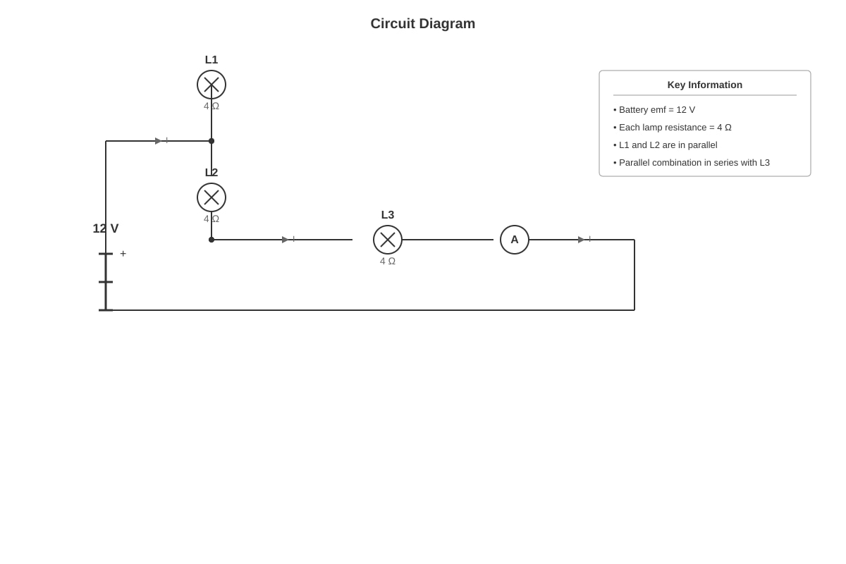
First, combined resistance of parallel pair (L1 and L2): [1 mark for method]
Total resistance: [1 mark]
(b) [2 marks]
Using Ohm's Law: [2 marks: 1 for formula, 1 for answer with unit]
Marking note: Accept 2 A or 2.0 A. Deduct 1 mark if no unit or wrong unit.
9. [4 marks]
(a) [2 marks]
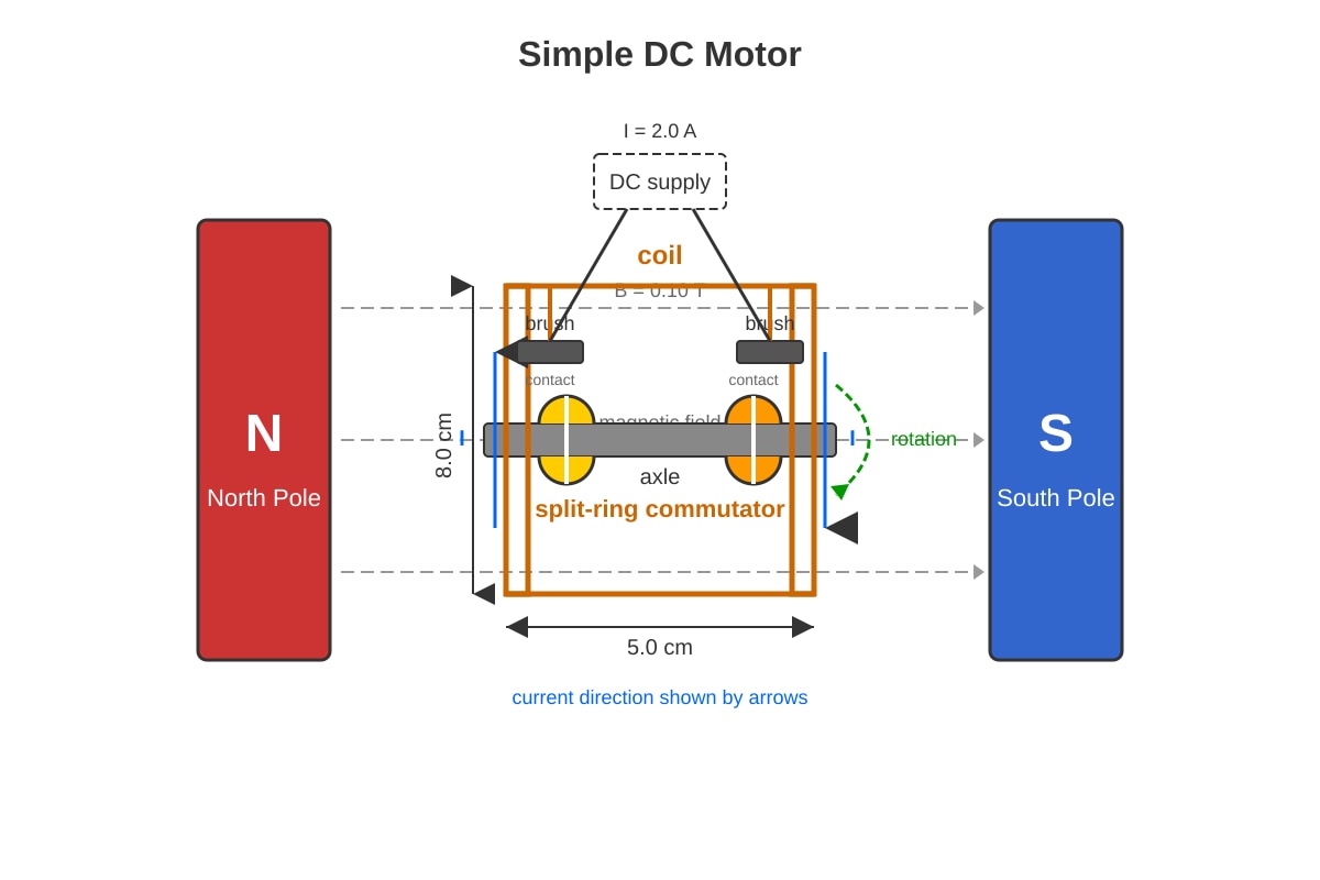
The split-ring commutator reverses the current direction in the coil every half rotation [1 mark]
This ensures the torque on the coil is always in the same direction, producing continuous rotation in one direction [1 mark]
Teaching note: Without the commutator, the coil would oscillate or stop at the vertical position. The commutator switches the current direction as the coil passes through the vertical (neutral) position, so the force on each side always produces rotation in the same sense.
(b) [2 marks]
Force on current-carrying conductor:
First convert: [1 mark for conversion or consistent working]
[1 mark]
Or N or 16 mN
Marking note: Deduct 1 mark if unit not converted (answer would be 1.6, which is numerically wrong). Accept 0.016 N or N with correct working.
10. [3 marks]
Apparatus: [Set-up description 1 mark]
- Ohmic conductor (e.g. constantan wire or resistor) at constant temperature (water bath or room temperature with brief measurements)
- Variable power supply or rheostat to vary p.d.
- Voltmeter connected in parallel with the conductor
- Ammeter connected in series
Method: [1 mark]
- Vary the p.d. using the variable supply/rheostat
- Record corresponding current readings
- Ensure temperature remains constant by using low currents or brief measurements
Verification: [1 mark]
- Plot graph of V against I
- Straight line through origin confirms Ohm's law (V ∝ I at constant temperature, so R is constant)
Marking descriptors:
- 1 mark: Correct circuit diagram description with meters correctly placed
- 1 mark: Method of varying p.d. and recording pairs of values
- 1 mark: Graphical verification with correct conclusion about straight line/proportionality
11. [3 marks]
(a) [1 mark]
(b) [2 marks]
Energy in one week: [1 mark]
Cost: 42 \times \0.25 = $10.50$ [1 mark]
Accept: 10.50
12. [3 marks]
(a) [1 mark]
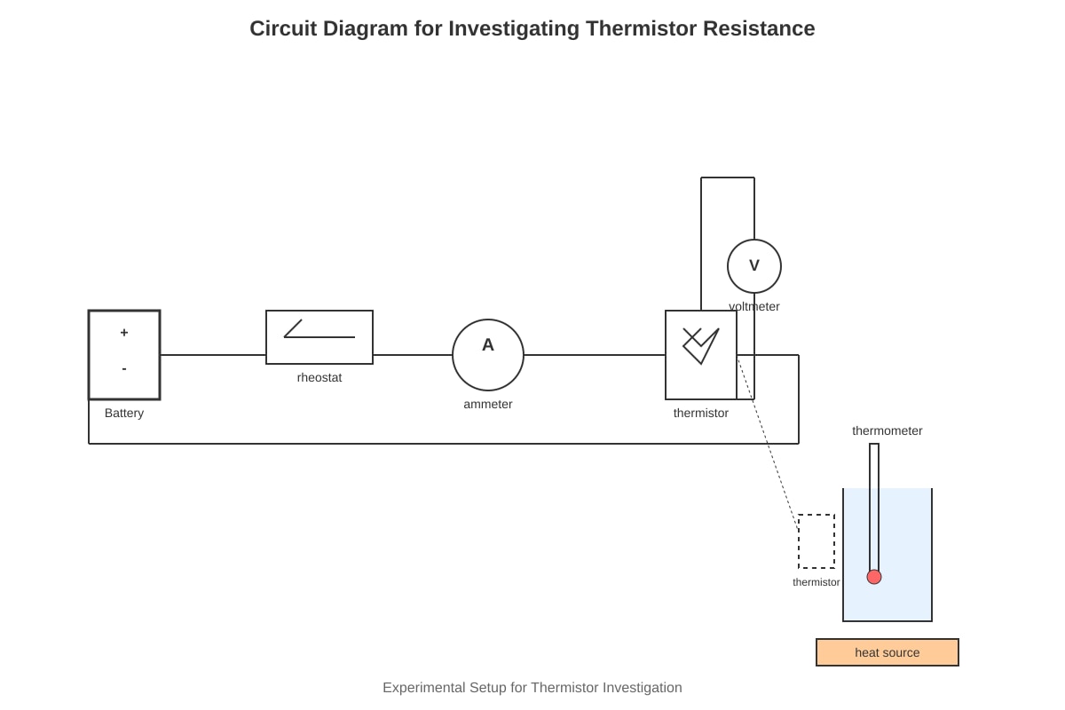
Using Ohm's Law: where V is the voltmeter reading and I is the ammeter reading
Accept description: Read V and I simultaneously, divide V by I
(b) [2 marks]
As temperature increases, the resistance of an NTC thermistor decreases [1 mark]
Practical use: Temperature sensor/thermostat/fire alarm [1 mark] — any one valid application
Teaching note: NTC = Negative Temperature Coefficient. The semiconductor material has more charge carriers freed at higher temperatures, so resistance drops. This is opposite to metallic conductors where resistance increases with temperature.
13. [3 marks]
(a) [1 mark]
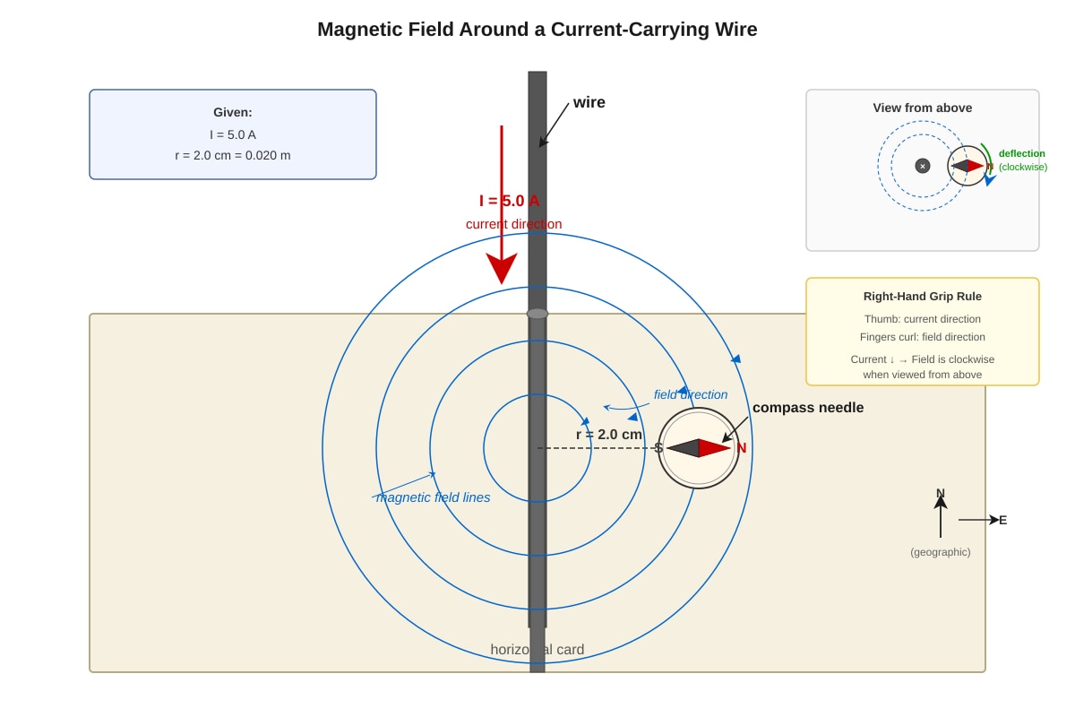
Clockwise (when viewed from above)
Reasoning: Using right-hand grip rule: thumb points down (current direction), fingers curl clockwise when viewed from above. The magnetic field below the wire (where compass is) is into the page, so N pole points east/clockwise.
(b) [2 marks]
[1 mark for substitution]
[1 mark]
Or: T or
Marking note: Must convert r = 2.0 cm = 0.020 m or 2.0 × 10⁻² m. Deduct 1 mark if axes confused (answer 5 × 10⁻³ T implies r = 2 m used).
14. [3 marks]
(a) [2 marks]
Soft iron [1 mark]
It has high magnetic permeability and becomes strongly magnetised in an external field, providing a low-reluctance path that diverts magnetic field lines away from the shielded region [1 mark]
(b) [1 mark]
Any valid answer: Shielding sensitive electronic equipment (e.g. MRI rooms, recording studios, oscilloscope enclosures), protecting compasses near strong magnets, shielding power cables
15. [3 marks]
(a) [1 mark]
Typical value: 15 A or 20 A (accept range 13–20 A for Singapore household circuits; standard MCB ratings are 15 A or 20 A for lighting, 30 A for power)
Teaching note: Singapore uses 230 V, 50 Hz supply. Lighting circuits typically protected by 15 A MCBs, power circuits by 30 A. Accept any reasonable stated value if consistent with explanation.
(b) [2 marks]
A fuse contains a thin wire that melts when current exceeds its rating [1 mark]
This breaks the circuit, stopping current flow and preventing overheating/damage to appliances or fire [1 mark]
Alternative: Circuit breaker works by electromagnet or thermal mechanism tripping a switch — accept if described correctly.
Section C: Application and Reasoning [10 marks]
16. [4 marks]
(a) [2 marks]
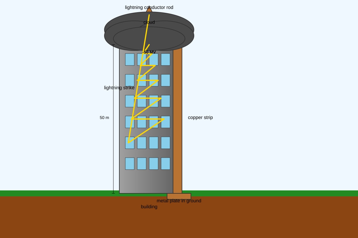
- Copper is used because it has very low electrical resistance (high conductivity), providing an easy path for the enormous lightning current to earth [1 mark]
- The strip is thick to provide low resistance and to carry very large currents without excessive heating or melting; it also provides mechanical strength [1 mark]
Marking note: Must mention both material choice and thickness reasoning. Accept "good conductor" for copper property. For thickness: low resistance AND ability to carry large current/thermal capacity.
(b) [2 marks]
The pointed conductor creates a strong electric field at its tip [1 mark]
This ionises air molecules (corona discharge), allowing charge to leak gradually from cloud to ground, preventing the buildup of potential difference that would cause a violent lightning strike [1 mark]
Alternative acceptable explanation: The conductor provides a preferred path for discharge, reducing likelihood of direct strike to building. Or: The air breakdown at the point creates a slow, controlled discharge (point action), preventing sudden large discharge. This is why lightning conductors are pointed, not blunt.
17. [4 marks]
(a) [2 marks]
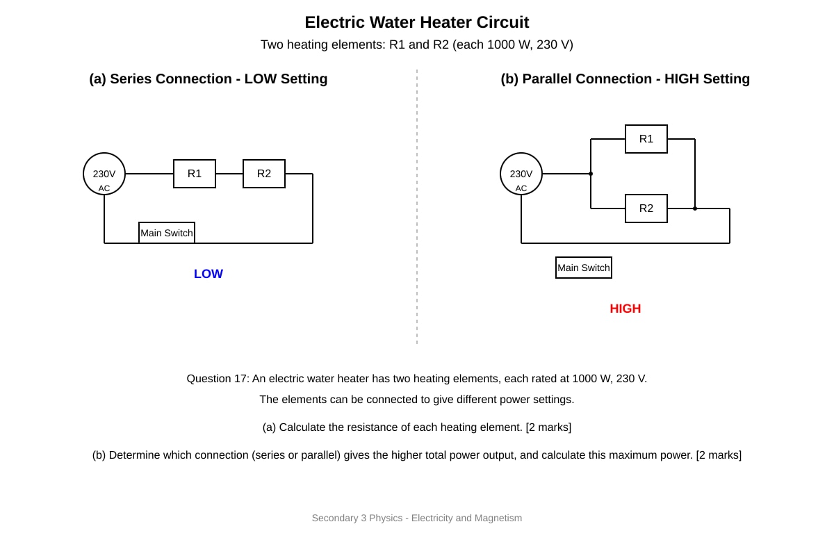
For one element: or
[2 marks: 1 for formula, 1 for answer]
Or using P = VI and V = IR: A, then
(b) [2 marks]
Parallel connection gives higher power [1 mark]
In parallel:
Or simply: each element receives full 230 V, so each delivers 1000 W, total 2000 W [1 mark]
Alternative for series: Ω, W, confirming parallel is higher.
Marking note: Must identify parallel as higher power setting. Calculation can be done by any valid method. Accept 2000 W or 2 kW.
18. [5 marks]
(a) [2 marks]
Any two from:
- Speed of relative motion between magnet and solenoid (faster movement = larger e.m.f.)
- Number of turns in the solenoid (more turns = larger e.m.f.)
- Strength of the magnet (stronger magnet = larger e.m.f.)
- Cross-sectional area of solenoid (larger area = more flux linkage change)
[1 mark each, max 2 marks]
(b) [1 mark]
No magnetic flux is being cut/changed / No change in magnetic flux linkage
Teaching note: Faraday's law states induced e.m.f. is proportional to rate of change of magnetic flux linkage. Stationary magnet = constant flux = zero rate of change = zero e.m.f.
(c) [2 marks]
Lenz's law states that the induced current flows in a direction to oppose the change causing it [1 mark]
When N pole is pushed in, the solenoid end nearest the magnet becomes a N pole (to repel the incoming N pole), so by right-hand grip rule, current flows anticlockwise when viewed from the magnet end [1 mark]
Alternatively: The induced current creates a magnetic field that opposes the increasing flux, hence the N pole is established to repel.
19. [3 marks]
(a) [1 mark]
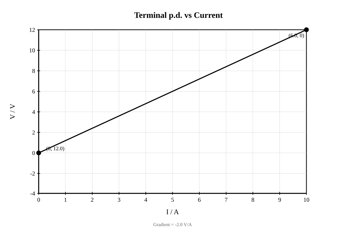
E.m.f. = 12.0 V (the intercept on the V-axis when I = 0)
Teaching note: When no current flows (open circuit), there is no voltage drop across internal resistance, so terminal p.d. equals e.m.f.
(b) [2 marks]
Internal resistance equals the negative gradient of the graph [1 mark]
[1 mark]
Or using any two points on the line, or from the formula V = ε - Ir
20. [5 marks]
(a) [2 marks]
For a given power (), higher voltage means lower current [1 mark]
Power loss in cables () is therefore much reduced, improving efficiency [1 mark]
Accept alternative: Lower current allows thinner cables/less copper, reducing cost and weight.
(b) [1 mark]
(c) [2 marks]
[1 mark for formula and working]
[1 mark]
Or: At 400 kV with 250 A, if voltage were 10 kV, current would be 10,000 A and losses dramatically higher. The 400 kV transmission reduces losses by factor of (400/10)² = 1600 compared to 10 kV transmission of same power.
END OF ANSWER KEY