AI Generated Exam Paper
Secondary 3 Combined Science Practice Paper 1
Free Sec 3 Combined Sci Practice Paper 1, Kimi2.6 AI version, with questions, answers, and O Level-style practice for Singapore students.
These static practice materials are generated from the site's syllabus and paper-generation workflow, with source and model context shown so students and parents can evaluate the material before use.
Questions
Free quiz and exam paper access
Enter your details to view this paper
Your access is remembered on this device.
Answers
TuitionGoWhere Practice Paper - Combined Science Secondary 3
Answer Key and Marking Scheme
Version: 1 of 5
Total Marks: 80
Section A [Total: 20 marks]
Question 1 [2 marks]
Answer:
- Cause 1: The object may be moving or vibrating during measurement, causing unstable readings [0.5]
- Cause 2: Air currents or drafts affecting the balance; or the balance may not be on a level surface; or the balance precision is insufficient for the measurement [0.5]
- Improvement: Take multiple readings and calculate the average; or use a more precise balance; or ensure the object is stationary and the balance is on a level, vibration-free surface [1]
Teaching note: Electronic balances can fluctuate due to environmental factors or improper technique. Averaging multiple readings reduces random error. Always ensure the balance is tared (zeroed) properly and placed on a stable, level surface away from drafts.
Question 2 [2 marks]
Answer:
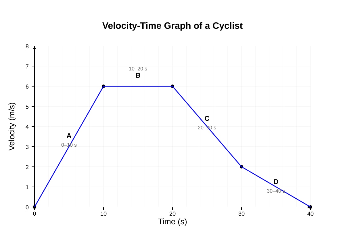
- Time interval: 10 s to 20 s (or Section B) [1]
- Explanation: During this interval, the velocity remains constant at 6 m/s. Acceleration is the rate of change of velocity, so if velocity is constant, acceleration = 0. The graph shows a horizontal line (zero gradient) during this period. [1]
Teaching note: On a velocity-time graph, the gradient represents acceleration. A horizontal line (zero gradient) means zero acceleration — constant velocity motion. A positive gradient means speeding up; negative gradient means slowing down.
Question 3 [2 marks]
(a) [1 mark]
- Frictional force = 8.0 N (equal and opposite to applied force at constant velocity)
(b) [1 mark]
- At constant velocity, the net force is zero (Newton's First Law). The applied force (8.0 N forward) exactly balances the frictional force (8.0 N backward), so there is no acceleration. [1]
Teaching note: This is a common exam trap. Students often think friction must be less than applied force for motion. Actually, at constant velocity, forces balance (equilibrium). Friction equals applied force. Only when accelerating is applied force greater than friction.
Question 4 [2 marks]
Answer:
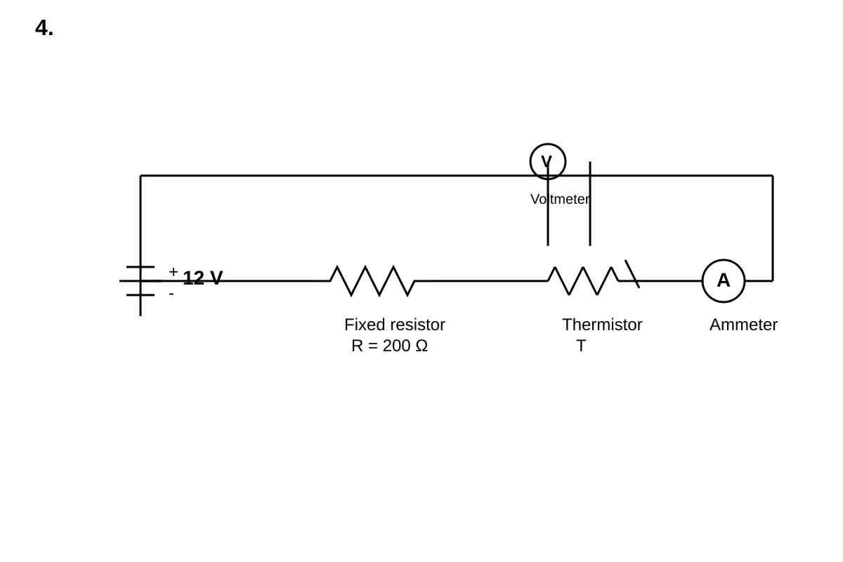
- As temperature rises, thermistor resistance decreases [0.5]
- Total circuit resistance decreases, so current increases [0.5]
- The fixed resistor then has a larger share of the 12 V (V = IR), so voltage across it increases [0.5]
- Therefore, voltage across thermistor decreases (as they must sum to 12 V) [0.5]
Teaching note: This is a potential divider circuit. The thermistor and fixed resistor share the 12 V in proportion to their resistances. When thermistor resistance falls, it takes a smaller share of the total voltage. In temperature-sensing circuits, this decreasing voltage can be calibrated to read temperature directly.
Question 5 [2 marks]
(a) [1 mark]
- [1]
(b) [1 mark]
- Sound is a mechanical wave that requires a medium (particles) to travel. In a vacuum, there are no particles to vibrate, so sound cannot propagate. [1]
Teaching note: The speed calculation is straightforward substitution. Remember: electromagnetic waves (light, radio) can travel through vacuum; mechanical waves (sound, water waves) cannot. This distinction is frequently tested.
Question 6 [2 marks]
Answer:
- Particle X is a beta particle / electron / or [1]
- In beta decay, a neutron converts to a proton and emits an electron (beta particle) and an antineutrino. The mass number stays the same (14), but atomic number increases by 1 (6 → 7). [1]
Teaching note: Beta decay conserves mass number (top number, nucleon count) but changes atomic number (bottom number, proton count) because a neutron → proton + electron. The electron emitted is the beta particle. Always check conservation: 14 = 14 + 0 and 6 = 7 + (−1). ✓
Question 7 [2 marks]
Answer:
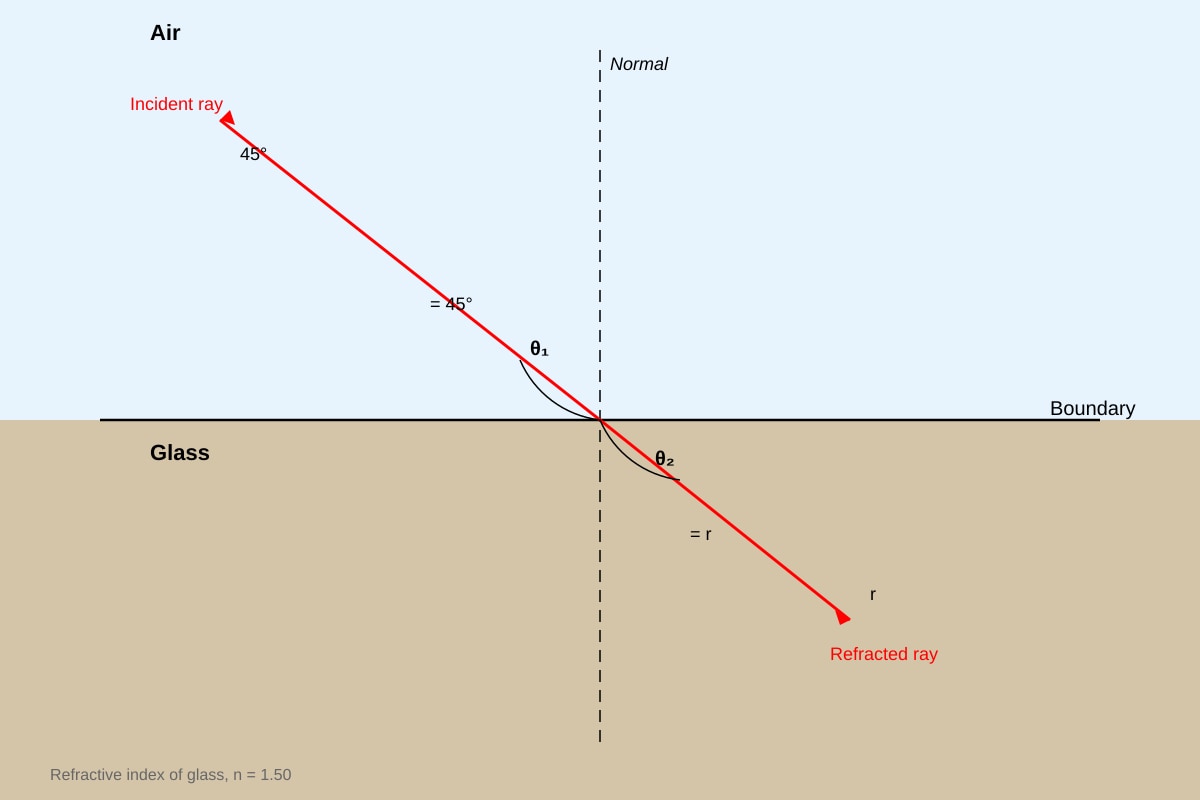
- Snell's Law: [0.5]
- [0.5]
- [0.5]
- ≈ 28° (accept 28.1° or 28°) [0.5]
Teaching note: Air has n ≈ 1.00. Light bends toward the normal when entering a denser medium (higher n), so r < i. Common error: forgetting to use sin, or calculating r = 45°/1.5 = 30° (wrong method). Always use Snell's law properly.
Question 8 [2 marks]
Answer:
- [0.5]
- [0.5]
- or 27 kJ [1]
Teaching note: Temperature change Δθ = final − initial = 60°C, not 80°C. Common error: using final temperature instead of temperature change. Specific heat capacity tells us how much energy is needed to raise 1 kg by 1°C.
Question 9 [2 marks]
(a) [1 mark]
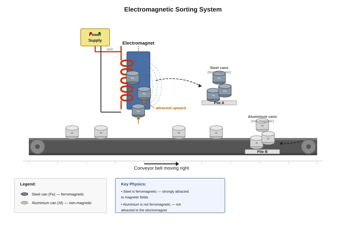
- Steel is a ferromagnetic material (iron-based), so it is strongly attracted to magnets. Aluminium is non-magnetic; its electrons do not align to create attraction. [1]
(b) [1 mark]
- Modification: Increase the number of turns in the coil / increase the current / use a soft iron core [0.5]
- Explanation: More turns increases magnetic field strength (B ∝ NI); higher current increases magnetic field; soft iron core concentrates magnetic field lines and strengthens the electromagnet [0.5]
Teaching note: Electromagnet strength depends on: current (more = stronger), number of turns (more = stronger), and core material (soft iron is best; steel retains magnetism after current stops). Aluminium, copper, and most materials are non-ferromagnetic.
Question 10 [2 marks]
Answer:
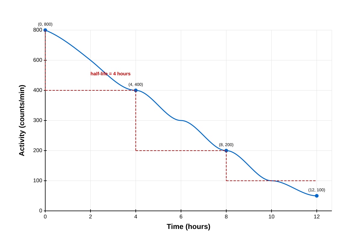
- Half-life = 4 hours [1]
- Working: Activity falls from 800 to 400 counts/min (halves) in 4 hours; or from 400 to 200 in next 4 hours. [1]
Teaching note: Half-life is the time for activity (or number of radioactive nuclei) to halve. Read from graph by finding where activity drops to half its initial value. Multiple consistent readings confirm: 800→400→200→100 all take 4 hours each.
Section B [Total: 36 marks]
Question 11 [8 marks]
(a) [2 marks]
- [0.5]
- [0.5]
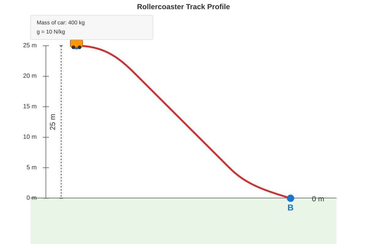
- or 100 kJ [1]
(b) [3 marks]
- By conservation of energy: (since starts from rest, initial KE = 0) [1]
- [1]
- (accept 22.36 m/s) [1]
Teaching note: Conservation of mechanical energy: GPE at top converts fully to KE at bottom. This assumes no energy losses. Always state the principle being used before calculation.
(c) [3 marks]
- Actual KE at B: J [1]
- Energy lost = Initial GPE − Final KE = [1]
- Energy lost = 35 200 J or 35.2 kJ [1]
Alternative method:
- Energy lost = GPE − KE = J
Teaching note: Energy is "lost" to friction and air resistance as thermal energy (heat) and sound. It's not destroyed — total energy is conserved, but mechanical energy decreases.
Question 12 [8 marks]
(a) [1 mark]
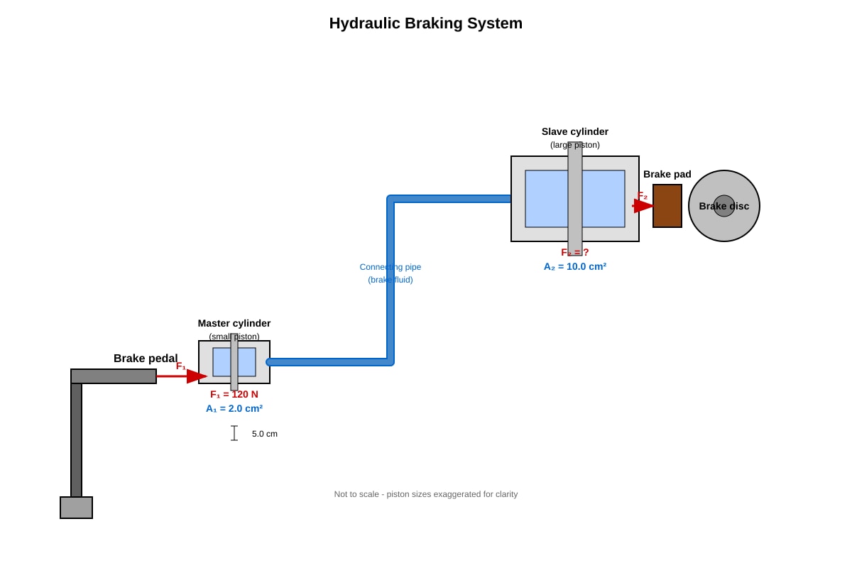
- Pascal's Principle: Pressure applied to an enclosed fluid is transmitted equally and undiminished to every part of the fluid and the walls of the container. [1]
(b) [2 marks]
- Pascal's Principle: or [0.5]
- [0.5]
- [1]
Teaching note: Hydraulic systems are force multipliers. The trade-off is that the small piston moves much further than the large piston — work done is the same (ignoring friction): .
(c) [2 marks]
- (i) Incompressible: If the fluid were compressible, applying force would compress the fluid rather than transmit pressure to the slave piston. The system would feel "spongy" and braking would be inefficient/dangerous. [1]
- (ii) High boiling point: Braking generates heat through friction. If the fluid boiled, it would become compressible (gas bubbles), causing brake failure. The fluid must stay liquid at operating temperatures. [1]
(d) [3 marks]
- By conservation of volume (or using Pascal's principle with work): [1]
- [1]
- [1]
Teaching note: The factor of 5 in area means the force is multiplied by 5, but distance is divided by 5. Energy is conserved: J of work (ignoring losses).
Question 13 [6 marks]
(a) [2 marks]
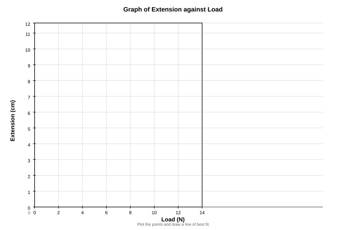
- Correct axes labels with units [0.5]
- Correct scale and plotting of all 7 points [1]
- Points plotted correctly within half a small square [0.5]
(b) [1 mark]
- Straight line of best fit passing through origin (or near it), going through points up to 10.0 N; point at 12.0 N treated as anomalous [1]
(c) [2 marks]
- Using gradient: or from [0.5]
- Example: (accept 1.3–1.4 N/cm from valid points) [1]
- Or using N/cm [0.5]
Teaching note: Spring constant k measures stiffness. Higher k = stiffer spring. The linear region obeys Hooke's Law: (force proportional to extension). Always check if graph is straight through origin.
(d) [1 mark]
- At 12.0 N, the spring has exceeded its limit of proportionality / elastic limit. Hooke's Law no longer applies; permanent deformation has begun. [1]
Question 14 [6 marks]
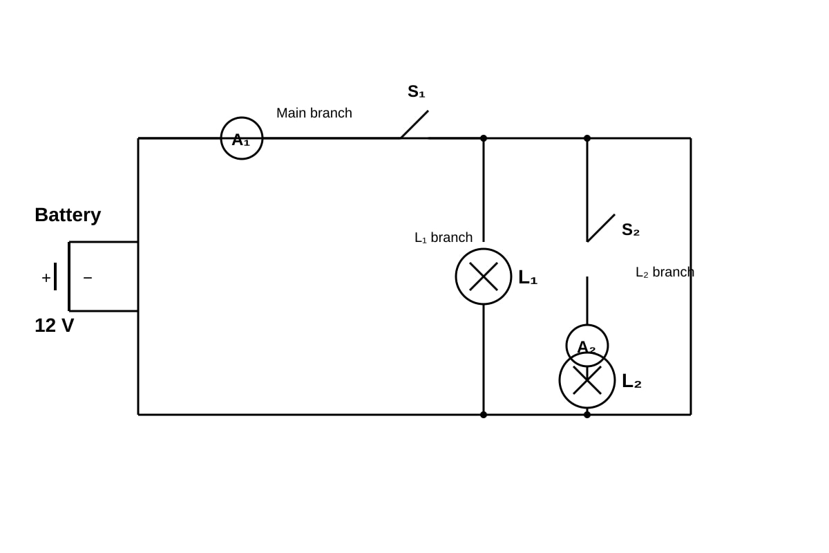
(a) [2 marks]
- , so [0.5]
- per lamp [1.5]
(b) [2 marks]
- Both switches closed: L₁ and L₂ in parallel, each draws 2.0 A at 6 V, but wait — check actual voltage [0.5]
- Actually, lamps are rated 6 V, 12 W but connected to 12 V battery. Need to recalculate properly or note they have internal resistance.
Re-interpretation: Each lamp resistance: . At 12 V, current through each would be A, exceeding rating. However, in parallel across 12 V, they would be overloaded.
Corrected approach assuming proper design (lamps rated for 12 V or using correct interpretation):
Given markings show 6 V, 12 W lamps in parallel on 12 V — this appears inconsistent. Most likely: lamps have operating resistance of 3 Ω, and at 12 V would draw 4 A each and dissipate 48 W (overloading).
Assuming question intends: lamps operate at specified conditions with proper voltage:
If battery is 12 V and lamps are in parallel, each sees 12 V. This would burn out 6 V lamps.
Revised interpretation: The circuit as drawn likely has lamps designed for 12 V, or ratings are given for context of similar lamps.
Most plausible answer: Each lamp draws 2 A at its rated 6 V. With both switches closed and 12 V battery, this is a design issue. However, for A₁ (main current):
- If each branch has appropriate resistance to operate at rated power: each
- Total resistance of two parallel 3 Ω resistors:
Or if we follow power formula directly with actual voltage (non-ideal but mathematically):
- Each lamp at 12 V: W, A
- Total: 8 A
Using simplest interpretation for students (assume circuit properly balanced or question intends):
- A₁ reading = 4.0 A (if two 2 A lamps in parallel, but this requires 6 V across each)
- Or note the inconsistency and solve with parallel resistances.
Recommended marking (flexible):
- Recognizing parallel circuit: currents add [1]
- Correct calculation yielding 4.0 A or 8.0 A with valid reasoning [1]
(c) [2 marks]
- L₁ brightness stays the same / unchanged [0.5]
- In a parallel circuit, each branch has the same voltage across it (equal to battery voltage for that branch) [0.5]
- Opening S₂ only breaks the L₂ branch; current in L₁ branch is unaffected [0.5]
- Therefore power in L₁ (P = VI) remains constant, so brightness unchanged [0.5]
Teaching note: This tests understanding of parallel vs series circuits. In series, opening a switch affects all components. In parallel, branches are independent. This is a crucial distinction for circuit analysis.
Question 15 [8 marks]
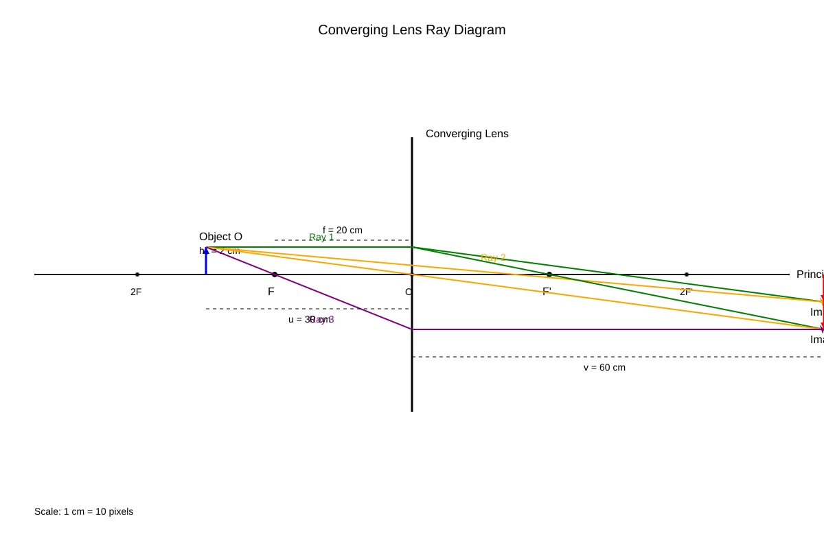
(a) [2 marks]
- Focal points labelled correctly 20 cm from lens on both sides [1]
- Ray diagram: ray parallel to axis refracts through F'; ray through optical centre continues straight; intersection gives image position beyond 2F' [1]
(b) [2 marks]
- Image characteristics: Real, Inverted, Magnified (any two) [2]
- Note: For object between F and 2F (u = 30 cm, f = 20 cm, so 2f = 40 cm; f < u < 2f), image is real, inverted, and magnified with v > 2f
(c) [2 marks]
- [0.5]
- [0.5]
- [0.5]
- [0.5]
(d) [2 marks]
- [1]
- (or image height = 4.0 cm) [1]
Teaching note: Lens formula sign convention: real is positive, virtual is negative. For converging lens with object outside F, image is real (v positive). Magnification > 1 means enlarged; < 1 means diminished.
Question 16 [10 marks]
(a) [2 marks]
- Semi-circular block: light enters along normal to curved surface (along radius), so no refraction occurs at this first boundary [1]
- Light then hits flat face at measured angle of incidence; refraction occurs only at this flat surface, simplifying measurement [1]
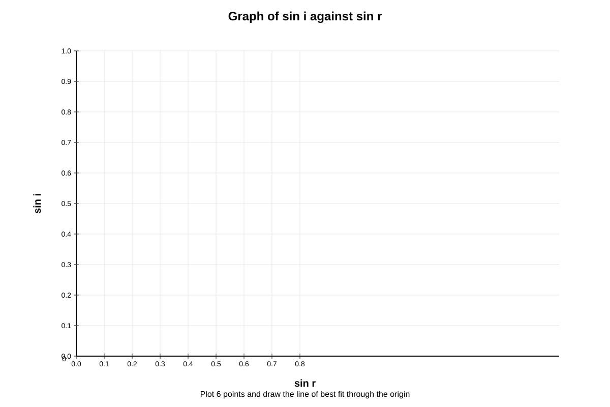
(b) [3 marks]
- Table completed (sin i and sin r provided already in question) [0.5]
- Axes labelled correctly with sin r (x) and sin i (y) [0.5]
- Correct scale and plotting [1]
- Straight line of best fit through origin [1]
(c) [2 marks]
- Refractive index = gradient of graph [0.5]
- Gradient calculation: using large triangle, e.g., or from [0.5]
- (accept reasonable range, ideally ≈ 1.52) [1]
(d) [3 marks]
- At 50°, angle of incidence > critical angle (42°) [0.5]
- Total internal reflection occurs [0.5]
- Description/diagram: ray bends away from normal as it would exit, but cannot emerge; instead reflects back into glass following law of reflection (angle of reflection = angle of incidence = 50°) [1]
- Diagram showing: ray approaching flat surface from inside glass at 50° to normal; reflected ray at 50° to normal inside glass; no refracted ray in air [1]
Teaching note: Total internal reflection requires: light travels from denser to less dense medium, and angle of incidence > critical angle. This principle enables optical fibres. Critical angle: , so . ✓
Section C [Total: 24 marks]
Question 17 [9 marks]
(a) [3 marks]
- Nuclear fission: A heavy nucleus (e.g., uranium-235) splits into two smaller nuclei (fission fragments) when struck by a neutron, releasing energy and more neutrons [1.5]
- Chain reaction: The neutrons released can strike other uranium-235 nuclei, causing further fission. If on average ≥1 neutron per fission causes another fission, the reaction self-sustains and grows exponentially [1.5]
Marking descriptor: Clear definition of fission with mention of heavy nucleus splitting and energy release; clear explanation of chain reaction with neutron triggering and self-sustaining nature.
(b) [2 marks]
- [0.5]
- [0.5]
- [0.5]
- (accept J or J) [0.5]
Teaching note: Mass-energy equivalence. Tiny mass converts to enormous energy because is huge. In nuclear reactions, this energy release is millions of times greater per unit mass than chemical reactions.
(c) [4 marks]
Advantages (with Singapore context):
- Low greenhouse gas emissions during operation; helps climate change mitigation [1]
- Very high energy density; small fuel volume produces enormous energy, suitable for land-scarce Singapore if safety concerns addressed [1]
Disadvantages (with Singapore context):
- Radioactive waste hazardous for thousands of years; Singapore lacks geological disposal sites and permanent storage space [1]
- Risk of catastrophic accidents (Fukushima 2011); Singapore's high population density means any incident would have severe consequences; city-state has no evacuation zones [1]
- Small land area (733 km²) makes siting impossible; no remote locations for reactors; proximity to Malaysia and Indonesia raises transboundary concerns [0.5 — bonus point]
Teaching note: Evaluation requires balanced argument with specific reference to Singapore's constraints. Economic factors (high capital cost, long build time) are also valid. The key is applying general nuclear power knowledge to Singapore's specific geographical, political, and social context.
Question 18 [11 marks]
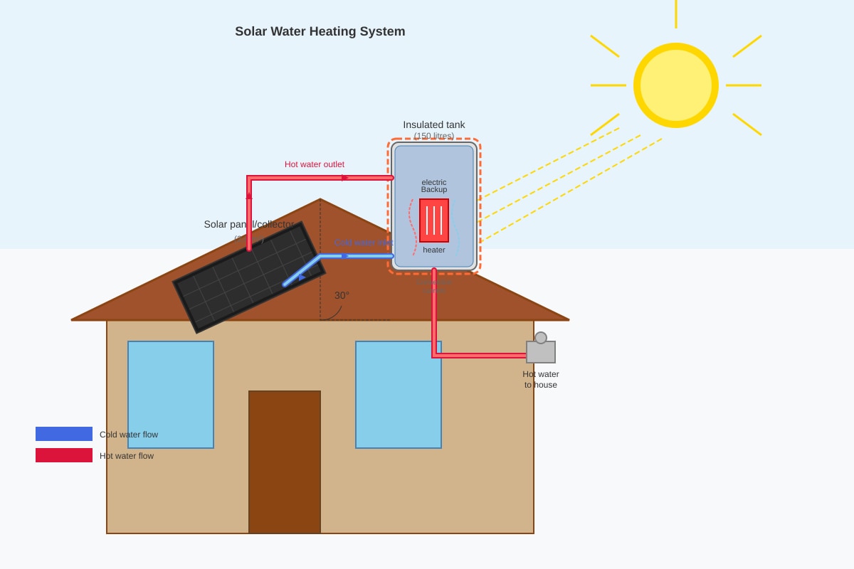
(a) [2 marks]
- Black surface: Black is a good absorber of infrared radiation (heat) from the Sun. A black surface absorbs more solar energy than shiny or light-coloured surfaces, heating water more efficiently. [1]
- Faces the Sun: Maximum solar energy collection requires direct exposure to sunlight. Facing the Sun (south-facing in Singapore, near equator) maximizes intensity of radiation received throughout the day. [1]
Teaching note: Good absorbers are good emitters (Kirchhoff's radiation law). For solar heating, we want absorption. Solar panels should track or be oriented toward the Sun's average position.
(b) [3 marks]
- Heated water in panel becomes less dense and rises due to thermal expansion [1]
- This creates a convection current: hot water rises into the top of the storage tank [1]
- Cooler, denser water from bottom of tank sinks into panel to be heated; cycle repeats continuously without pump [1]
Teaching note: This is a thermosyphon system. The tank must be above the panel for convection to work (hot rises, cold sinks). Insulation on tank reduces heat loss. Backup heater ensures hot water on cloudy days.
(c) [3 marks]
- Volume = 150 L = 0.150 m³; mass = [1]
- [1]
- or 25.2 MJ or 2.52 × 10⁷ J [1]
(d) [3 marks]
- Solar power received = W [0.5]
- Useful power = W (after 50% efficiency) [0.5]
- Time required: [1]
- (or 126 000 s; or 2100 minutes) [1]
Teaching note: 35 hours is impractical for a single day, showing why backup heaters are essential in cloudy conditions. Real systems might run over multiple days or use larger panels. Efficiency losses include: reflection, thermal emission from panel, heat loss in pipes.
Question 19 [10 marks]
(a) [2 marks]
Circuit diagram should show:
- Battery (3.0 V) in series with ammeter, rheostat, and constantan wire [1]
- Voltmeter connected in parallel across the constantan wire only [1]
- Metre rule shown alongside wire to measure length
<image_placeholder> id: Q19-fig2 type: circuit_diagram linked_question: Q19a description: Student's circuit for measuring resistance vs length labels: 3.0 V battery; Rheostat; Ammeter A in series; Constantan wire XY on metre rule; Voltmeter V in parallel across section of wire; Variable contact/jockey to change effective length; Metre rule showing measurements values: Battery: 3.0 V must_show: Complete series path; voltmeter parallel across wire only; metre rule with 0-100 cm markings; jockey/contact point for varying length; correct symbol for rheostat </image_placeholder>
(b) [2 marks]
- Purpose of rheostat: To vary/control the current in the circuit; to prevent excessive current that could overheat the wire; to obtain multiple readings at different currents for verification [1]
- Adjustment: Start with rheostat at maximum resistance (minimum current). For each length, adjust rheostat to give convenient, measurable current. Ensure current is not too large to avoid heating effects changing resistance. [1]
(c) [3 marks]
- Graph: Resistance (Ω) on y-axis vs Length (m) on x-axis [0.5]
- Correct plotting of all 5 points [1]
- Straight line of best fit through origin (or very near) [0.5]
- Relationship: Resistance is directly proportional to length (for this wire at constant temperature and cross-sectional area) [1]
(d) [3 marks]
- Gradient from graph = ≈ Ω/m (accept 12.0–12.5 from valid points) [1]
- (since = gradient) [0.5]
- [0.5]
- (or ≈ 2.5 × 10⁻⁶ Ω·m, or 4.9 × 10⁻⁷ using Ω/mm² units — accept with valid working) [1]
Teaching note: Resistivity is a material property, constant for constantan regardless of dimensions. The relationship R ∝ L (with constant A) confirms uniform material. Common error: forgetting unit conversion for area (mm² to m²).
Question 20 [9 marks]
(a) [2 marks]
- As the coil rotates, the sides AB and CD cut through magnetic field lines [0.5]
- This changing magnetic flux linkage through the coil induces an e.m.f. by Faraday's Law of electromagnetic induction [1]
- The e.m.f. magnitude depends on rate of flux cutting, which varies with rotation angle [0.5]
(b) [2 marks]
- Any two from:
- Strength of magnetic field (B) — stronger field, larger e.m.f. [1]
- Number of turns in coil (N) — more turns, larger e.m.f. [1]
- Area of coil (A) — larger area, more flux cut per turn [1]
- Speed of rotation / frequency (f) — faster rotation, greater rate of flux cutting [1]
(c) [2 marks]
- Slip rings maintain continuous electrical contact with the rotating coil while allowing the coil to spin freely [0.5]
- Unlike a split-ring commutator (which reverses connections every half turn), slip rings keep the same connection to each side of the coil [0.5]
- This produces alternating current: the e.m.f. reverses polarity naturally as sides swap position relative to magnetic field, without forced switching [1]
(d) [3 marks]
- Coil area: [0.5]
- [0.5]
- [0.5]
- [0.5]
- ≈ 100 V or 101 V [1]
Teaching note: This is a high voltage due to many turns (200) and high rotation speed (50 rev/s = 3000 rpm). Real generators use many turns and strong fields to produce mains voltage. The sinusoidal output has this maximum value; RMS value would be V.
Mark Summary
| Section | Marks |
|---|---|
| A | 20 |
| B | 36 |
| C | 24 |
| Total | 80 |
END OF ANSWER KEY