From Real Exams Exam Paper
O Level Physics Practice Paper 3
Free O Level Physics Practice Paper 3, Gemma31B Exam version, with questions, answers, and O Level-style practice for Singapore students.
These static practice materials are generated from the site's syllabus and paper-generation workflow, with source and model context shown so students and parents can evaluate the material before use.
Questions
Free quiz and exam paper access
Enter your details to view this paper
Your access is remembered on this device.
Answers
Answer Key - Physics O-Level Practice Paper (Version 3)
Section A: Structured Questions
Q1 (a) Thermistor is an NTC (Negative Temperature Coefficient) resistor. As temperature increases, resistance of thermistor decreases. Total resistance , so total resistance decreases. [2] (b) [1] (c) [2]
Q2 (a) [2] (b) [2] (c) [2]
Q3 (a) [2] (b) Power . Since is halved (from 240 to 120), decreases by a factor of 4 (assuming is constant). Thus, actual power is , which is less than 60W. [2]
Q4 (a) The resistance of the wire is equal to the resistance of the fixed resistor (). [1] (b) Since and , . [2]
Q5 (a) Fleming's Left-Hand Rule. [1] (b) It reverses the direction of the current in the coil every half rotation, ensuring the force always acts in the same rotational direction. [2] (c) 1. Increase current (increase battery voltage). 2. Increase number of turns in the coil / use a stronger permanent magnet. [2]
Q6 (a) Step-up transformer. [1] (b) . [2] (c) High voltage reduces the current for the same power transmission (). Lower current reduces energy loss as heat () in the transmission cables. [3]
Q7 (a) 1. Increase current in the coil. 2. Increase number of turns of the coil. [2] (b) Soft iron is easily magnetized and demagnetized (low retentivity), allowing the relay to switch on and off quickly. Steel is a permanent magnet and would stay magnetized. [2]
Q8 (a) The EMF varies sinusoidally over time, alternating between positive and negative maximum values. [2] (b) Increase the speed of rotation / increase number of turns in the coil / use a stronger magnet. [1]
Q9 (a) As light intensity increases, resistance of LDR decreases. In a potential divider, the voltage across the LDR decreases. [2] (b) Automatic street lights / light sensors. [1]
Q10 (a) To protect the circuit from excessive current. It melts and breaks the circuit if current exceeds its rating, preventing overheating/fires. [2] (b) The fuse will blow/melt. Because the appliance draws , which exceeds the rating of the fuse. [2]
Section B: Application and Analysis
Q11 (a) Thermistor (for temperature) and LDR (for light). [2] (b)
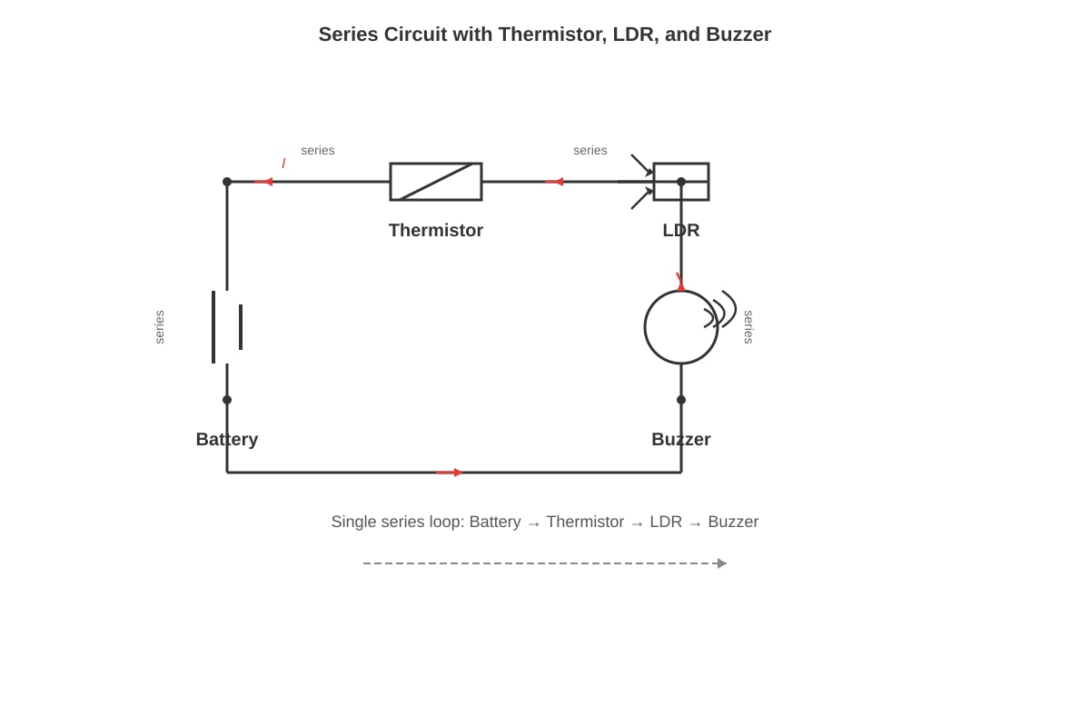
Generated diagram for this question.
. [4] (c) In a series circuit, the buzzer only sounds if the total resistance is low enough to allow sufficient current. When , thermistor resistance drops; when light , LDR resistance increases (Wait: for "AND" logic in series, both must be low resistance). Correction for student: Both sensors must be in series with the buzzer, and the buzzer activates when both resistances are low. [3]
Q12 (a) [2] (b) [1] (c) The direction of the force will be reversed (opposite to original direction). [2]
Q13 (a) Series: Same current flows through all components. Parallel: Current splits between branches. [2] (b) Series: Voltage is shared (sum of voltages = supply). Parallel: Each branch has the same voltage as the supply. [2] (c) 1. Independent operation: one appliance can be turned off without affecting others. 2. Constant voltage: each appliance receives the full mains voltage to operate at rated power. [3]
Q14 (a) The movement of the magnet creates a changing magnetic flux through the coil, which induces an EMF/current. [2] (b) Lenz's Law. [1] (c) 1. Move the magnet faster. 2. Use a stronger magnet / increase number of turns in the coil. [2]
Q15 (a) To provide a low-resistance path to earth for current if a fault occurs. [2] (b) If a live wire touches the metal casing, the current flows to earth, causing the fuse to blow and disconnecting the supply, preventing electric shock. [2] (c) To complete the circuit by providing a return path for the current. [1]
Q16 (a) Total resistance increases (since one parallel path is removed). Since , the total current decreases. [3] (b) The voltage remains the same (it is still connected to the same supply voltage). [2]
Q17 (a) Strong and uniform (parallel straight lines). [1] (b) Increase current / increase number of turns per unit length / insert a soft iron core. [2]
Q18 (a) If the variable resistor is in parallel with the LED, increasing its resistance increases the total resistance of that section. However, if it's a divider, increasing the series resistor increases voltage across the LED. [3] (Mark based on circuit interpretation: usually refers to the "control" resistor in the divider).
Q19 (a) [2] (b) Energy loss due to heat in the coils (resistance) / flux leakage / eddy currents. [1]
Q20 (a) The current-carrying wire creates a magnetic field around it. This field interacts with the magnetic field of the compass needle, exerting a force/torque. [2] (b) The deflection will increase (stronger magnetic field). [1]