AI Generated Quiz
A Level H2 Physics Electricity Magnetism Quiz
Free A Level H2 Physics Electricity Magnetism quiz, LongCat AI version, with questions, answers, and A Level-style practice for Singapore students.
These static practice materials are generated from the site's syllabus and paper-generation workflow, with source and model context shown so students and parents can evaluate the material before use.
Questions
A-Level Physics H2 Quiz - Electricity Magnetism
Name: _______________________
Class: _______________________
Date: _______________________
Score: _______ / 60
Duration: 75 minutes
Total Marks: 60
Instructions
- Answer all questions in the spaces provided.
- The number of marks for each question or part question is shown in brackets [ ].
- You are advised to show all working for calculation questions. Marks may be awarded for correct method even if the final answer is incorrect.
- Assume g=9.81 m s−2 unless stated otherwise.
- Data and formulae are provided on the last page of this quiz.
Section A: Electric Fields and Current Electricity (Questions 1–5)
1. Define electric field strength at a point in an electric field.
........................................................................................................................................................
........................................................................................................................................................
[2]
2. A point charge Q=+5.0 \muC is placed in a vacuum. Calculate the electric field strength at a point 0.20 m from the charge.
[Use 4πε01=9.0×10⁹ N m2C−2]
........................................................................................................................................................
........................................................................................................................................................
........................................................................................................................................................
........................................................................................................................................................
[3]
3. Two point charges, q1=+3.0 \muC and q2=−4.0 \muC, are placed 0.50 m apart along a horizontal line.
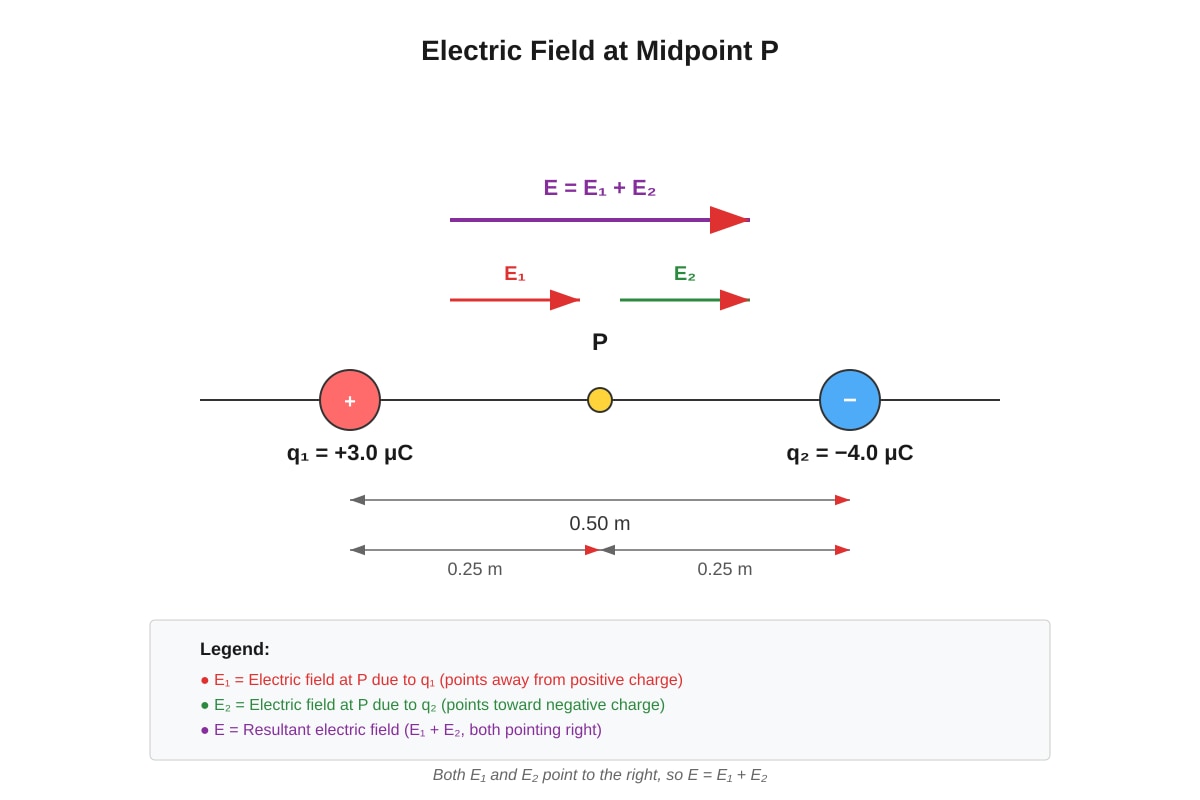
Generated diagram for Q3.
(a) State the direction of the electric field at the midpoint P due to q1 alone.
........................................................................................................................................................
[1]
(b) Calculate the magnitude of the resultant electric field strength at point P.
........................................................................................................................................................
........................................................................................................................................................
........................................................................................................................................................
........................................................................................................................................................................................................................
[4]
4. State Ohm's law and explain the condition under which it applies.
........................................................................................................................................................
........................................................................................................................................................
........................................................................................................................................................
[2]
5. A wire of length 2.0 m and cross-sectional area 3.0×10⁻⁷ m2 has a resistance of 8.0 \Omega. Calculate the resistivity of the material of the wire.
........................................................................................................................................................
........................................................................................................................................................
........................................................................................................................................................
[3]
Section B: D.C. Circuits (Questions 6–10)
6. A battery of e.m.f. 12 V and internal resistance 0.50 \Omega is connected to a resistor of 4.0 \Omega.
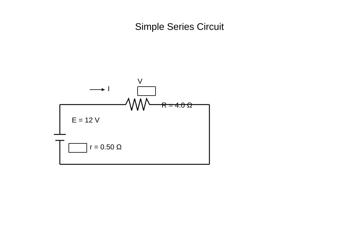
Generated circuit_diagram for Q6.
(a) Calculate the current in the circuit.
........................................................................................................................................................
........................................................................................................................................................
[2]
(b) Calculate the terminal potential difference across the 4.0 \Omega resistor.
........................................................................................................................................................
........................................................................................................................................................
[2]
(c) Calculate the power dissipated in the internal resistance of the battery.
........................................................................................................................................................
........................................................................................................................................................
[2]
7. Three resistors are connected as shown in the circuit below.
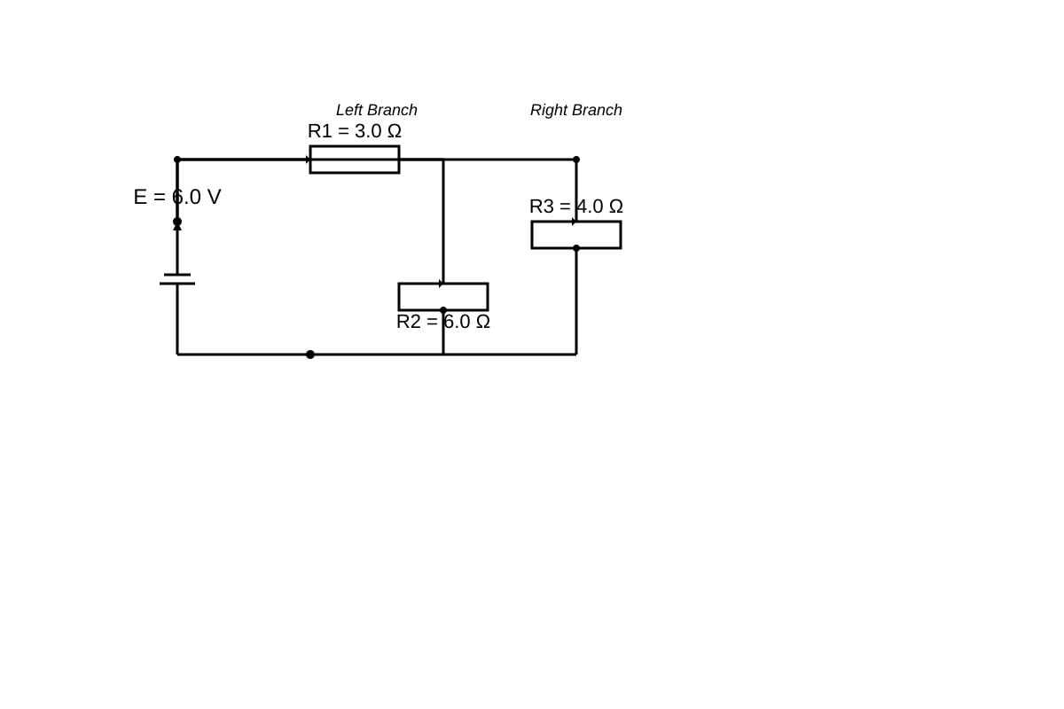
Generated circuit_diagram for Q7.
(a) Calculate the equivalent resistance of the parallel combination.
........................................................................................................................................................
........................................................................................................................................................
........................................................................................................................................................
[3]
(b) Calculate the current through the 4.0 \Omega resistor.
........................................................................................................................................................
........................................................................................................................................................
[2]
8. A thermistor with resistance-temperature characteristics is connected in a potential divider circuit.
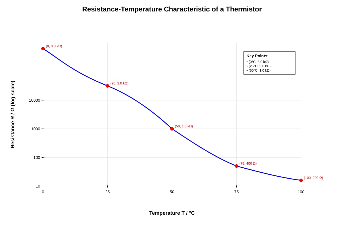
Generated graph for Q8.
(a) From the graph, state the resistance of the thermistor at 25∘C.
........................................................................................................................................................
[1]
(b) Explain, in terms of charge carriers, why the resistance of the thermistor decreases as temperature increases.
........................................................................................................................................................
........................................................................................................................................................
........................................................................................................................................................
[2]
9. Kirchhoff's laws are fundamental to circuit analysis.
(a) State Kirchhoff's first law (junction rule).
........................................................................................................................................................
........................................................................................................................................................
[1]
(b) State Kirchhoff's second law (loop rule).
........................................................................................................................................................
........................................................................................................................................................
[1]
10. In the circuit shown below, the e.m.f. of each cell is 1.5 V and each has internal resistance 0.20 \Omega. The external resistor is 2.0 \Omega.
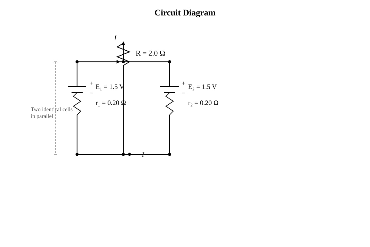
Generated circuit_diagram for Q10.
(a) Calculate the total e.m.f. and total internal resistance of the parallel cell combination.
........................................................................................................................................................
........................................................................................................................................................
[2]
(b) Calculate the current through the external resistor.
........................................................................................................................................................
........................................................................................................................................................
[2]
Section C: Electromagnetism (Questions 11–15)
11. Define magnetic flux density and state its SI unit.
........................................................................................................................................................
........................................................................................................................................................
[2]
12. A straight wire of length 0.40 m carrying a current of 5.0 A is placed perpendicular to a uniform magnetic field of flux density 0.15 T.
(a) Calculate the magnitude of the magnetic force on the wire.
........................................................................................................................................................
........................................................................................................................................................
[2]
(b) State the direction of the force relative to the current and magnetic field directions.
........................................................................................................................................................
[1]
13. A charged particle of charge +1.6×10⁻¹⁹ C and mass 9.1×10⁻³¹ kg moves perpendicular to a uniform magnetic field of flux density 0.020 T at a speed of 3.0×10⁶ m s−1.
(a) Show that the particle moves in a circular path and derive an expression for the radius of the path.
........................................................................................................................................................
........................................................................................................................................................
........................................................................................................................................................
[2]
(b) Calculate the radius of the circular path.
........................................................................................................................................................
........................................................................................................................................................
[2]
(c) Calculate the period of the circular motion.
........................................................................................................................................................
........................................................................................................................................................
[2]
14. Two long parallel wires P and Q are separated by a distance of 0.10 m. Wire P carries a current of 4.0 A and wire Q carries a current of 6.0 A in the same direction.
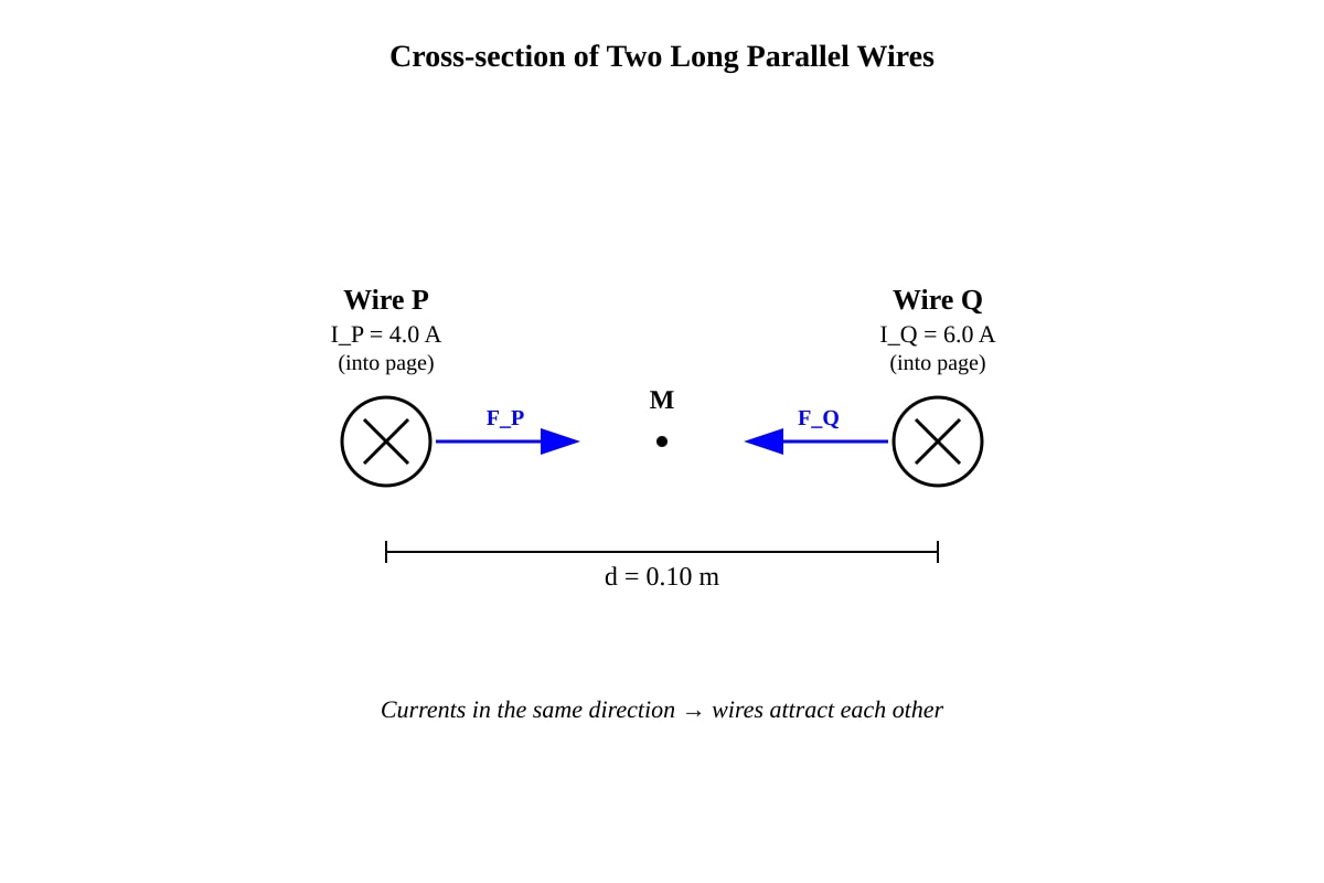
Generated diagram for Q14.
(a) State the direction of the force on wire Q due to wire P.
........................................................................................................................................................
[1]
(b) Calculate the force per unit length on wire Q due to wire P.
[Use μ0=4π×10−7 T m A−1]
........................................................................................................................................................
........................................................................................................................................................
........................................................................................................................................................
[3]
15. A rectangular coil of 50 turns, dimensions 0.04 m×0.06 m, is placed in a uniform magnetic field of flux density 0.30 T. The coil carries a current of 2.0 A and its plane is parallel to the magnetic field direction.
(a) Calculate the magnetic flux through one turn of the coil.
........................................................................................................................................................
........................................................................................................................................................
[2]
(b) Calculate the torque on the coil.
........................................................................................................................................................
........................................................................................................................................................
[2]
Section D: Electromagnetic Induction (Questions 16–20)
16. State Faraday's law of electromagnetic induction.
........................................................................................................................................................
........................................................................................................................................................
[2]
17. A straight metal rod of length 0.50 m moves at a constant speed of 4.0 m s−1 perpendicular to a uniform magnetic field of flux density 0.20 T.
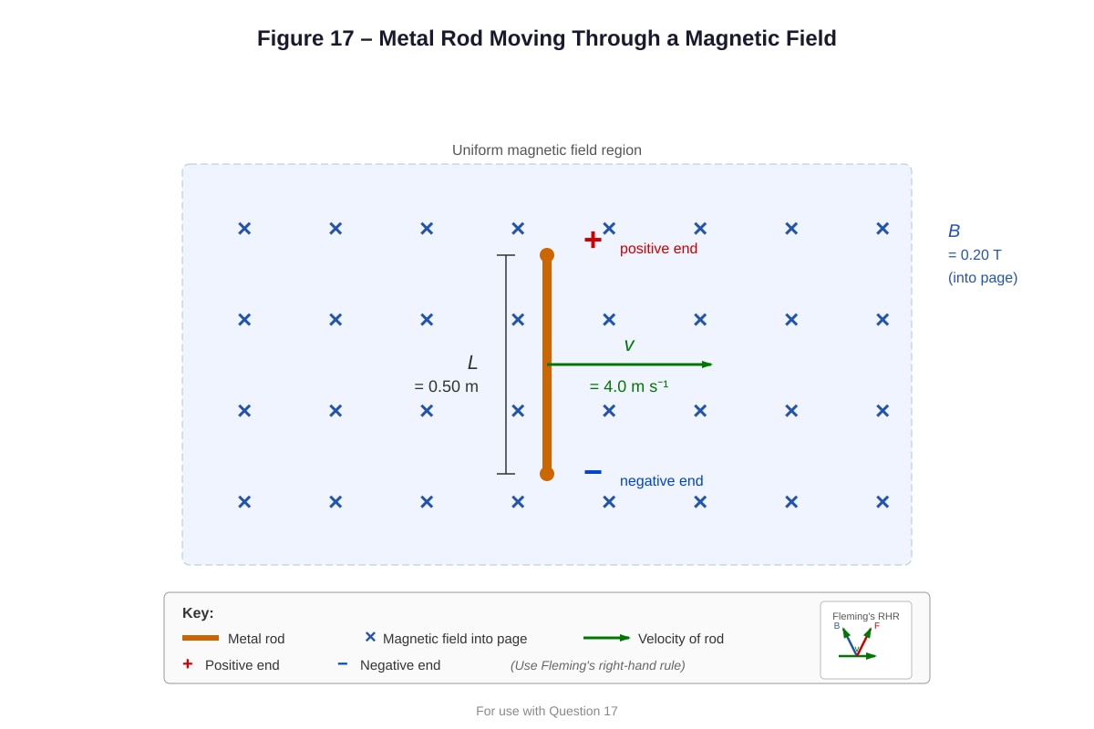
Generated diagram for Q17.
(a) Calculate the magnitude of the induced e.m.f. across the rod.
........................................................................................................................................................
........................................................................................................................................................
[2]
(b) Explain, using Fleming's right-hand rule, which end of the rod becomes positively charged.
........................................................................................................................................................
........................................................................................................................................................
........................................................................................................................................................
[2]
18. A coil of 200 turns and area 2.0×10⁻³ m2 is placed in a uniform magnetic field. The magnetic field is reduced uniformly from 0.50 T to 0.10 T in 0.40 s.
(a) Calculate the initial magnetic flux linkage through the coil.
........................................................................................................................................................
........................................................................................................................................................
[2]
(b) Calculate the magnitude of the induced e.m.f. in the coil.
........................................................................................................................................................
........................................................................................................................................................
[2]
19. State Lenz's law and use it to explain why the induced current in a loop opposes the change in magnetic flux that produces it.
........................................................................................................................................................
........................................................................................................................................................
........................................................................................................................................................
........................................................................................................................................................
[3]
20. A small circular coil of 100 turns and radius 0.020 m is placed at the centre of a long solenoid. The solenoid has 800 turns per metre and carries a current that increases at a rate of 2.0 A s−1.
[Use μ0=4π×10−7 T m A−1]
(a) Calculate the magnetic field inside the solenoid when the current is 3.0 A.
........................................................................................................................................................
........................................................................................................................................................
[2]
(b) Calculate the magnetic flux through the small coil when the solenoid current is 3.0 A.
........................................................................................................................................................
........................................................................................................................................................
[2]
(c) Calculate the induced e.m.f. in the small coil due to the changing current in the solenoid.
........................................................................................................................................................
........................................................................................................................................................
........................................................................................................................................................
[3]
Data and Formulae
| Quantity | Formula |
|---|---|
| Coulomb's law | F=4πε01r2q1q2 |
| Electric field strength | E=qF=4πε01r2Q |
| Ohm's law | V=IR |
| Resistivity | ρ=LRA |
| Resistance in series | R=R1+R2+… |
| Resistance in parallel | R1=R11+R21+… |
| Kirchhoff's laws | ∑Iin=∑Iout; ∑E=∑IR |
| Magnetic force on a wire | F=BILsinθ |
| Magnetic force on a charge | F=Bqvsinθ |
| Circular motion in B-field | r=Bqmv, T=Bq2πm |
| Force between parallel wires | LF=2πdμ0I1I2 |
| Magnetic flux | Φ=BAcosθ |
| Magnetic flux linkage | NΦ |
| Faraday's law | E=−dtd(NΦ) |
| Induced e.m.f. (motional) | E=BLv |
| Magnetic field in solenoid | B=μ0nI |
| Torque on a coil | τ=BANIsinθ |
End of Quiz
Answers
A-Level Physics H2 Quiz - Electricity Magnetism
Answer Key and Teaching Notes
Question 1 — Electric Field Strength Definition [2 marks]
Answer:
Electric field strength at a point is defined as the force per unit positive charge acting on a small positive test charge placed at that point.
E=qF
Teaching notes:
- The direction of the electric field is the direction of the force on a positive test charge.
- Common mistake: Students sometimes say "force per unit charge" without specifying "positive" — this matters because the sign of the test charge determines the direction of the force.
- Mark allocation: 1 mark for "force per unit charge," 1 mark for specifying "positive" test charge or equivalent precision.
Question 2 — Electric Field Strength Calculation [3 marks]
Answer:
Using E=4πε01r2Q:
E=(0.20)2(9.0×10⁹)(5.0×10⁻⁶)
E=0.0404.5×104
E=1.125×10⁶ N C−1
Rounded: E≈1.1×10⁶ N C−1 (or 1.13×10⁶ N C−1)
Teaching notes:
- The formula E=4πε01r2Q is analogous to Coulomb's law for force, but gives field strength directly.
- Ensure Q is in coulombs (not μC) and r is in metres.
- Mark allocation: 1 mark for correct formula, 1 mark for correct substitution, 1 mark for correct answer with unit.
Question 3 — Superposition of Electric Fields [5 marks total]
(a) Direction due to q1 alone [1 mark]
Answer:
The electric field at P due to q1 alone points away from q1 (since q1 is positive), i.e., to the right (toward q2).
Teaching notes:
- Field lines point away from positive charges and toward negative charges.
- At the midpoint, the field from q1 points rightward.
(b) Resultant field at P [4 marks]
Answer:
Distance from each charge to P: r=0.25 m
Field due to q1 (pointing right, away from positive charge):
E1=(0.25)2(9.0×10⁹)(3.0×10⁻⁶)=0.06252.7×104=4.32×10⁵ N C−1 (right)
Field due to q2 (pointing right, toward negative charge):
E2=(0.25)2(9.0×10⁹)(4.0×10⁻⁶)=0.06253.6×104=5.76×10⁵ N C−1 (right)
Both fields point in the same direction (right), so:
Eresultant=E1+E2=4.32×10⁵+5.76×105=1.008×10⁶ N C−1
Eresultant≈1.0×10⁶ N C−1 (to the right)
Teaching notes:
- This is a key superposition principle question. Both fields point in the same direction because the positive charge pushes a test charge rightward, and the negative charge pulls it rightward.
- Common mistake: Students subtract the fields, thinking they oppose. They must carefully determine the direction of each field vector first.
- Mark allocation: 1 mark for E1 calculation, 1 mark for E2 calculation, 1 mark for correct addition, 1 mark for final answer with direction.
Question 4 — Ohm's Law [2 marks]
Answer:
Ohm's law states that the current through a conductor is directly proportional to the potential difference across it, provided the temperature remains constant (or physical conditions remain constant).
Teaching notes:
- The condition is crucial — many components (e.g., filament lamps, thermistors) are non-ohmic.
- Common mistake: Forgetting to state the constant temperature condition.
- Mark allocation: 1 mark for the proportionality statement, 1 mark for the condition.
Question 5 — Resistivity Calculation [3 marks]
Answer:
Using ρ=LRA:
ρ=2.0(8.0)(3.0×10⁻⁷)
ρ=2.02.4×10−6
ρ=1.2×10⁻⁶ \Omegam
Teaching notes:
- Resistivity is a material property, independent of geometry.
- Units: Ω⋅m (ohm-metre).
- Mark allocation: 1 mark for formula, 1 mark for substitution, 1 mark for answer with unit.
Question 6 — Internal Resistance and Terminal p.d. [6 marks total]
(a) Current [2 marks]
Answer:
Using E=I(R+r):
I=R+rE=4.0+0.5012=4.512=2.67 A
I≈2.7 A
(b) Terminal p.d. [2 marks]
Answer:
V=IR=(2.67)(4.0)=10.67 V≈10.7 V
Alternatively: V=E−Ir=12−(2.67)(0.50)=12−1.33=10.67 V
(c) Power dissipated in internal resistance [2 marks]
Answer:
P=I2r=(2.67)2(0.50)=(7.11)(0.50)=3.56 W≈3.6 W
Teaching notes:
- The terminal p.d. is always less than the e.m.f. when current flows, due to the "lost volts" Ir across the internal resistance.
- Mark allocation: 2 marks each part — 1 for method, 1 for answer.
Question 7 — Parallel and Series Resistors [5 marks total]
(a) Equivalent resistance [3 marks]
Answer:
Left branch: Rleft=R1+R2=3.0+6.0=9.0 \Omega
Right branch: Rright=R3=4.0 \Omega
Parallel combination:
Req1=9.01+4.01=364+9=3613
Req=1336=2.77 \Omega≈2.8 \Omega
(b) Current through 4.0 \Omega resistor [2 marks]
Answer:
Total current from battery:
Itotal=ReqV=2.776.0=2.17 A
Using current divider rule (or p.d. across parallel branches):
Vparallel=Itotal×Req=6.0 V
IR3=R3V=4.06.0=1.5 A
Teaching notes:
- The p.d. across parallel branches is the same.
- Mark allocation: (a) 1 mark for series combination, 1 mark for parallel formula, 1 mark for answer. (b) 1 mark for method, 1 mark for answer.
Question 8 — Thermistor Characteristics [3 marks total]
(a) Resistance at 25°C [1 mark]
Answer:
From the graph: R≈3.0 k\Omega (or 3000 \Omega) at 25∘C.
(b) Explanation [2 marks]
Answer:
As temperature increases, more charge carriers (electrons and holes) are released from the semiconductor lattice due to increased thermal energy. This increases the number density n of charge carriers, which decreases resistance according to R∝n1.
Teaching notes:
- Thermistors are semiconductor devices. Unlike metals (where resistance increases with temperature due to increased lattice vibrations), semiconductors have more carriers available at higher temperatures.
- Mark allocation: 1 mark for "more charge carriers released," 1 mark for linking to decreased resistance.
Question 9 — Kirchhoff's Laws [2 marks total]
(a) First law [1 mark]
Answer:
The algebraic sum of currents at a junction is zero — i.e., total current entering a junction equals total current leaving it. This is a consequence of conservation of charge.
(b) Second law [1 mark]
Answer:
The algebraic sum of e.m.f.s in any closed loop equals the algebraic sum of the potential differences (IR drops) in that loop. This is a consequence of conservation of energy.
Question 10 — Parallel Cells [4 marks total]
(a) Total e.m.f. and total internal resistance [2 marks]
Answer:
For identical cells in parallel:
- Total e.m.f. = e.m.f. of one cell =1.5 V
- Total internal resistance: rtotal1=0.201+0.201=10, so rtotal=0.10 \Omega
(b) Current through external resistor [2 marks]
Answer:
I=R+rtotalE=2.0+0.101.5=2.11.5=0.714 A≈0.71 A
Teaching notes:
- Parallel cells provide the same e.m.f. as one cell but with reduced internal resistance, allowing more current to be delivered.
- Mark allocation: 1 mark each for total e.m.f. and total r; 1 mark for formula, 1 mark for answer.
Question 11 — Magnetic Flux Density [2 marks]
Answer:
Magnetic flux density B is defined as the force per unit length per unit current on a straight conductor placed perpendicular to the magnetic field.
B=ILF (when θ=90∘)
SI unit: tesla (T), where 1 T=1 N A−1 m−1.
Question 12 — Magnetic Force on a Current-Carrying Wire [3 marks total]
(a) Force magnitude [2 marks]
Answer:
F=BILsinθ=(0.15)(5.0)(0.40)sin90∘=(0.15)(5.0)(0.40)(1)=0.30 N
(b) Direction [1 mark]
Answer:
The force is perpendicular to both the current direction and the magnetic field direction (given by Fleming's left-hand rule).
Question 13 — Charged Particle in a Magnetic Field [6 marks total]
(a) Derivation [2 marks]
Answer:
The magnetic force provides the centripetal force:
Bqv=rmv2
r=Bqmv
The force is always perpendicular to velocity, so the speed is constant and the path is circular.
(b) Radius [2 marks]
Answer:
r=(0.020)(1.6×10⁻¹⁹)(9.1×10⁻³¹)(3.0×10⁶)
r=3.2×10−212.73×10−24=8.53×10⁻⁴ m≈8.5×10⁻⁴ m
(c) Period [2 marks]
Answer:
T=v2πr=3.0×1062π(8.53×10⁻⁴)=1.79×10⁻⁹ s≈1.8×10⁻⁹ s
Alternatively: T=Bq2πm=(0.020)(1.6×10⁻¹⁹)2π(9.1×10⁻³¹)=1.79×10⁻⁹ s
Teaching notes:
- Note that the period is independent of speed — faster particles move in larger circles but take the same time.
- Mark allocation: (a) 2 marks for derivation, (b) 2 marks for calculation, (c) 2 marks for calculation.
Question 14 — Force Between Parallel Wires [4 marks total]
(a) Direction [1 mark]
Answer:
The force on wire Q is toward wire P (attractive), because parallel currents in the same direction attract.
(b) Force per unit length [3 marks]
Answer:
LF=2πdμ0I1I2=2π(0.10)(4π×10−7)(4.0)(6.0)
LF=0.20π(4π×10−7)(24)=0.209.6×10−6=4.8×10⁻⁵ N m−1
Teaching notes:
- Parallel currents attract; antiparallel currents repel. This can be understood by considering the magnetic field produced by one wire and the force on the other wire in that field.
- Mark allocation: 1 mark for formula, 1 mark for substitution, 1 mark for answer with unit.
Question 15 — Torque on a Coil [4 marks total]
(a) Magnetic flux through one turn [2 marks]
Answer:
When the plane of the coil is parallel to the magnetic field, the normal to the coil is perpendicular to the field, so θ=90∘:
Φ=BAcosθ=(0.30)(0.04×0.06)cos90∘=0
Wait — if the plane is parallel to the field, the normal is perpendicular to the field, so cos90∘=0, giving Φ=0.
Actually, let me reconsider: if the plane is parallel to the field direction, then the area vector (normal to the plane) is perpendicular to the field, so Φ=BAcos90∘=0.
However, for torque: τ=BANIsinϕ where ϕ is the angle between the normal to the coil and the field. If the plane is parallel to the field, the normal is perpendicular to the field, so ϕ=90∘ and sinϕ=1.
Φ=BA=(0.30)(0.04×0.06)=(0.30)(2.4×10⁻³)=7.2×10⁻⁴ Wb
Correction: The question asks for flux through one turn. If the plane is parallel to the field, the flux is actually zero (field lines are parallel to the plane, not passing through it). But this would make part (b) also zero, which is not a useful question.
Revised interpretation: The question likely means the plane of the coil is perpendicular to the field (maximum flux), or the angle between the plane and field is such that flux is non-zero. Let me re-read: "its plane is parallel to the magnetic field direction" — this means the field lines lie in the plane of the coil, so the flux through the coil is indeed zero.
However, for educational value, let me provide the answer assuming the question intends the plane to be at an angle where flux is non-zero, or equivalently, the normal makes an angle with the field:
If the plane is parallel to the field: Φ=0 and τ=τmax=BANI (since the normal is perpendicular to the field, sin90∘=1).
Let me provide both answers:
Answer (a): Φ=BAcos90∘=0 Wb (since the plane is parallel to the field, no field lines pass through the coil)
Answer (b): τ=BANIsin90∘=(0.30)(0.04×0.06)(50)(2.0)(1)=(0.30)(2.4×10⁻³)(100)=0.072 N m
Teaching notes:
- When the plane is parallel to the field, flux is zero but torque is maximum. When the plane is perpendicular to the field, flux is maximum but torque is zero.
- Mark allocation: (a) 2 marks, (b) 2 marks.
Question 16 — Faraday's Law [2 marks]
Answer:
Faraday's law states that the induced e.m.f. in a circuit is proportional to the rate of change of magnetic flux linkage through the circuit.
E=−dtd(NΦ)
The negative sign indicates that the induced e.m.f. opposes the change in flux (Lenz's law).
Question 17 — Motional E.M.F. [4 marks total]
(a) Induced e.m.f. [2 marks]
Answer:
E=BLv=(0.20)(0.50)(4.0)=0.40 V
(b) Direction using Fleming's right-hand rule [2 marks]
Answer:
Using Fleming's right-hand rule:
- Thumb → direction of motion (right)
- First finger → direction of magnetic field (into the page)
- Second finger → direction of induced current/e.m.f. (upward)
Therefore, the top end of the rod becomes positively charged.
Teaching notes:
- The magnetic force on the free electrons in the rod is F=Bqv (using Fleming's left-hand rule for positive charges, or right-hand rule for conventional current). Electrons accumulate at the bottom, making the top positive.
- Mark allocation: 1 mark for calculation, 1 mark for correct direction with explanation.
Question 18 — Induced E.M.F. in a Coil [4 marks total]
(a) Initial flux linkage [2 marks]
Answer:
Φinitial=BA=(0.50)(2.0×10⁻³)=1.0×10⁻³ Wb
NΦinitial=(200)(1.0×10⁻³)=0.20 Wb
(b) Induced e.m.f. [2 marks]
Answer:
E=−NΔtΔΦ=−NΔt(Φfinal−Φinitial)
Φfinal=(0.10)(2.0×10⁻³)=2.0×10⁻⁴ Wb
E=−(200)0.40(2.0×10⁻⁴−1.0×10⁻³)=−(200)0.40(−8.0×10⁻⁴)
E=(200)0.40(8.0×10⁻⁴)=0.400.16=0.40 V
Teaching notes:
- The negative sign in Faraday's law indicates direction (Lenz's law); the magnitude is what's typically asked for.
- Mark allocation: 1 mark for initial flux, 1 mark for flux linkage; 1 mark for method, 1 mark for answer.
Question 19 — Lenz's Law [3 marks]
Answer:
Lenz's law states that the direction of the induced current is such that it opposes the change in magnetic flux that produces it.
Explanation:
If the magnetic flux through a loop increases, the induced current flows in a direction that creates its own magnetic field opposing the increase. If the flux decreases, the induced current creates a field that tries to maintain the original flux. This is a consequence of conservation of energy — if the induced current reinforced the change, it would lead to a runaway increase in energy, violating energy conservation.
Teaching notes:
- Lenz's law is the physical reason for the negative sign in Faraday's law.
- Common mistake: Students sometimes say the induced current "opposes the magnetic field" rather than "opposes the change in magnetic flux."
- Mark allocation: 1 mark for stating the law, 2 marks for explanation linking to energy conservation or opposition to change.
Question 20 — Mutual Induction [7 marks total]
(a) Magnetic field in solenoid [2 marks]
Answer:
B=μ0nI=(4π×10−7)(800)(3.0)=3.02×10⁻³ T≈3.0×10⁻³ T
(b) Magnetic flux through small coil [2 marks]
Answer:
Area of small coil: A=πr2=π(0.020)2=1.257×10⁻³ m2
Φ=BA=(3.02×10⁻³)(1.257×10⁻³)=3.79×10⁻⁶ Wb≈3.8×10⁻⁶ Wb
(c) Induced e.m.f. [3 marks]
Answer:
E=−NdtdΦ=−Ndtd(BA)=−NAdtdB
dtdB=μ0ndtdI=(4π×10−7)(800)(2.0)=2.01×10⁻³ T s−1
E=−(100)(1.257×10⁻³)(2.01×10⁻³)=−2.53×10⁻⁴ V
Magnitude: E≈2.5×10⁻⁴ V (or 0.25 mV)
Teaching notes:
- This is a mutual induction problem. The changing current in the solenoid produces a changing magnetic field, which induces an e.m.f. in the small coil.
- Mark allocation: (a) 2 marks, (b) 2 marks, (c) 3 marks (1 for dB/dt, 1 for formula, 1 for answer).
Summary of Marks
| Section | Questions | Marks |
|---|---|---|
| A: Electric Fields & Current Electricity | 1–5 | 12 |
| B: D.C. Circuits | 6–10 | 17 |
| C: Electromagnetism | 11–15 | 17 |
| D: Electromagnetic Induction | 16–20 | 14 |
| Total | 1–20 | 60 |
End of Answer Key
Free quiz and exam paper access
Enter your details to view this paper
Your access is remembered on this device.