From Real Exams Quiz
A Level H2 Physics Electricity Magnetism Quiz
Free A Level H2 Physics Electricity Magnetism quiz, LongCat Exam version, with questions, answers, and A Level-style practice for Singapore students.
These static practice materials are generated from the site's syllabus and paper-generation workflow, with source and model context shown so students and parents can evaluate the material before use.
Questions
A-Level Physics H2 Quiz - Electricity Magnetism
Name: _______________________
Class: _______________________
Date: _______________________
Score: _______ / 60
Duration: 60 minutes
Total Marks: 60
Instructions
- Answer ALL questions in the spaces provided.
- Show all working clearly. Answers without working may not receive full credit.
- The number of marks for each question is given in brackets [ ].
- You may use a calculator.
- Take g=9.81 m s−2 where needed.
- Fundamental constants are provided where required.
Section A: Electric Fields and Current Electricity (Questions 1–5)
1. State Coulomb's Law in words and write its mathematical expression.
Define all symbols used.
[3]
2. Two point charges Q1=+4.0 \muC and Q2=−6.0 \muC are placed 0.30 m apart in a vacuum.
(a) Calculate the magnitude of the electrostatic force between the two charges.
[2]
(b) State whether the force is attractive or attractive, and explain your reasoning.
[1]
(c) A third charge Q3=+2.0 \muC is placed on the line joining Q1 and Q2, exactly midway between them. Calculate the magnitude and direction of the resultant force on Q3.
[4]
3. The figure below shows a uniform electric field between two parallel plates.
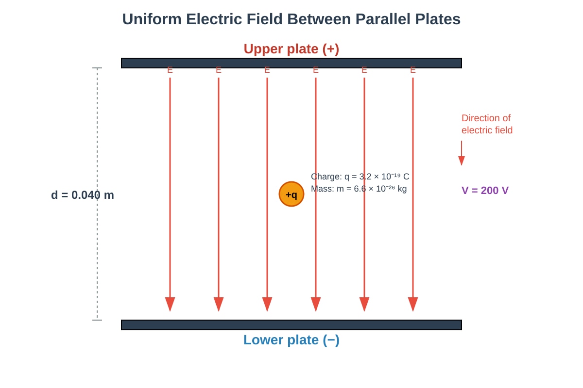
Generated diagram for Q3.
(a) Calculate the electric field strength between the plates.
[2]
(b) Calculate the force on the charged particle due to the electric field.
[2]
(c) The particle is released from rest at the positive plate. Calculate its speed just before it reaches the negative plate.
[3]
4. Define electric potential at a point in an electric field.
Explain how it differs from electric potential energy.
[3]
5. A student sets up the circuit shown below to investigate the I-V characteristics of a filament lamp.
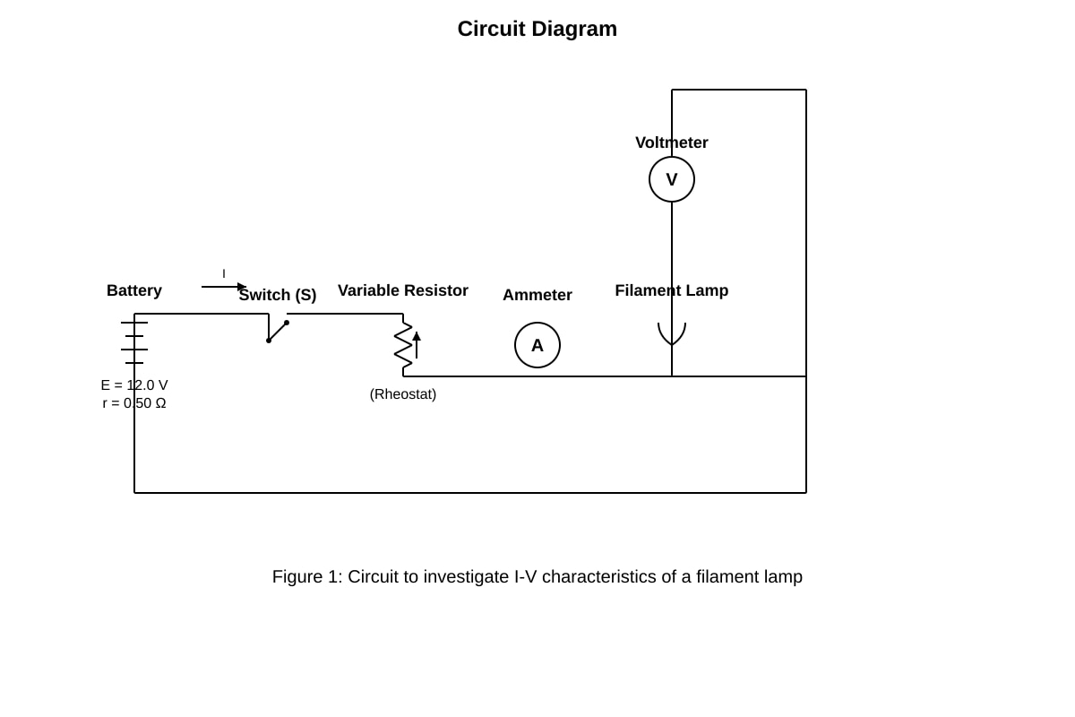
Generated experimental_setup for Q5.
(a) Explain why the variable resistor is necessary in this circuit.
[2]
(b) The student records the following data:
| V / V | 0.0 | 1.0 | 2.0 | 3.0 | 4.0 | 5.0 | 6.0 |
|---|---|---|---|---|---|---|---|
| I / A | 0.00 | 0.12 | 0.22 | 0.30 | 0.37 | 0.43 | 0.48 |
(i) Plot a graph of I against V on the grid provided.
[3]
(ii) Use your graph to determine the resistance of the lamp at V=4.0 V.
[2]
(iii) Explain why the resistance of the filament lamp changes with voltage.
[2]
Section B: D.C. Circuits (Questions 6–10)
6. State Kirchhoff's First Law (Junction Rule).
State the physical principle on which it is based.
[2]
7. For the circuit shown below, calculate the current through the 6.0 \Omega resistor.
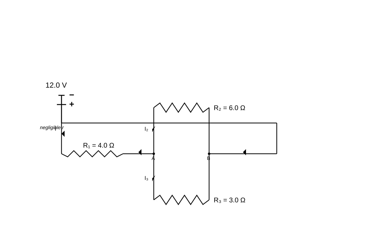
Generated diagram for Q7.
[4]
8. A cell of emf 1.50 V and internal resistance 0.20 \Omega is connected to an external resistor of 2.80 \Omega.
(a) Calculate the terminal potential difference across the cell.
[2]
(b) Calculate the power dissipated in the external resistor.
[2]
(c) Explain what happens to the terminal potential difference when the external resistance is decreased.
[2]
9. A potential divider circuit is shown below.
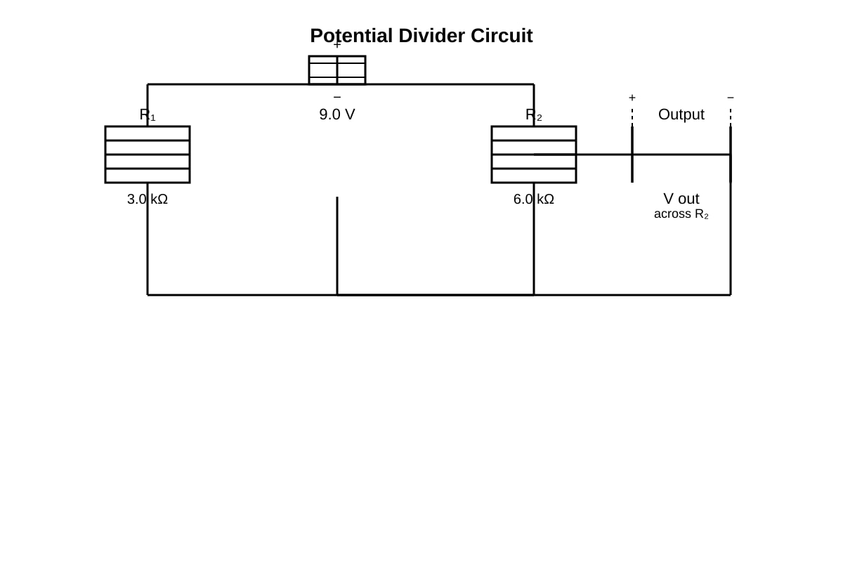
Generated diagram for Q9.
(a) Calculate the output voltage across R2.
[2]
(b) A load resistor of 12.0 k\Omega is now connected in parallel with R2. Calculate the new output voltage.
[3]
(c) Explain why the output voltage changes when the load is connected.
[2]
10. A battery of emf 12.0 V and internal resistance 1.0 \Omega is connected to a network of resistors as shown.
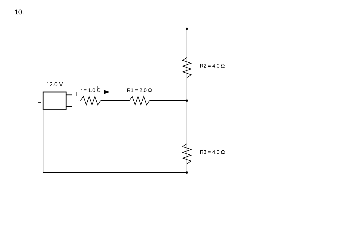
Generated diagram for Q10.
(a) Calculate the total resistance of the external circuit.
[2]
(b) Calculate the current drawn from the battery.
[2]
(c) Calculate the power dissipated in the internal resistance of the battery.
[2]
Section C: Electromagnetism (Questions 11–15)
11. Define magnetic flux density.
State its SI unit and give its symbol.
[2]
12. A straight wire of length 0.50 m carrying a current of 4.0 A is placed perpendicular to a uniform magnetic field of flux density 0.20 T.
(a) Calculate the magnetic force on the wire.
[2]
(b) The wire is now rotated so that it makes an angle of 30∘ with the magnetic field. Calculate the new force on the wire.
[2]
(c) State two ways in which the force on the wire can be increased.
[2]
13. A rectangular coil of 50 turns, dimensions 0.040 m×0.060 m, carries a current of 2.0 A. The coil is placed in a uniform magnetic field of flux density 0.15 T such that the plane of the coil is parallel to the field.
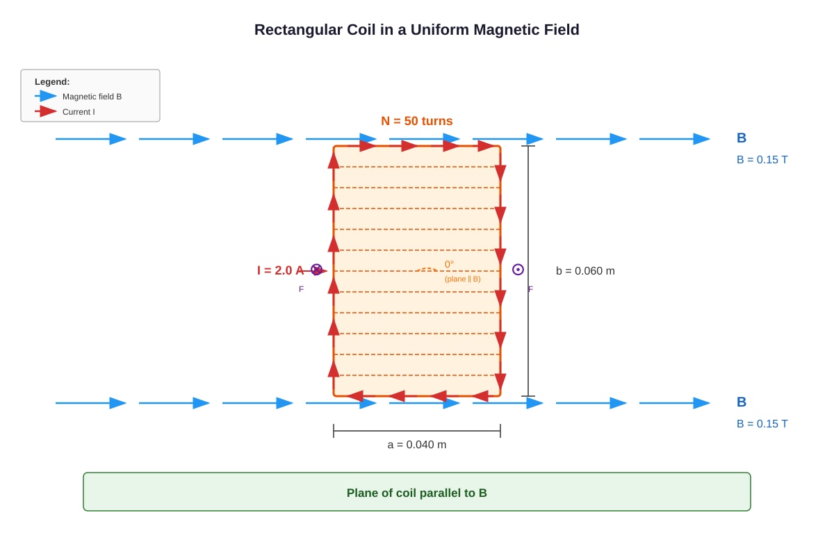
Generated diagram for Q13.
(a) Calculate the magnetic flux through one turn of the coil.
[2]
(b) Calculate the torque on the coil.
[3]
(c) Explain what happens to the torque if the number of turns is doubled.
[1]
14. A charged particle of mass 9.11×10⁻³¹ kg and charge −1.60×10⁻¹⁹ C moves perpendicular to a uniform magnetic field of flux density 0.050 T with a speed of 3.0×10⁶ m s−1.
(a) Calculate the magnetic force on the particle.
[2]
(b) Show that the particle moves in a circular path and calculate the radius of the path.
[3]
(c) Calculate the time taken for the particle to complete one full revolution.
[2]
15. Two long straight parallel wires P and Q are placed 0.10 m apart in a vacuum. Wire P carries a current of 5.0 A and wire Q carries a current of 8.0 A in the same direction.
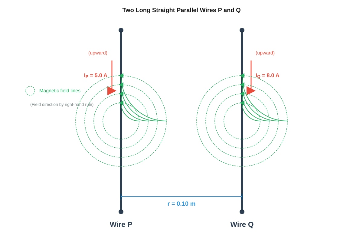
Generated diagram for Q15.
(a) Calculate the magnetic flux density at the position of wire Q due to the current in wire P.
[2]
(b) Calculate the force per unit length on wire Q due to the magnetic field from wire P.
[2]
(c) State whether the force between the wires is attractive or repulsive, and explain your reasoning.
[2]
Section D: Electromagnetic Induction (Questions 16–20)
16. State Faraday's Law of Electromagnetic Induction.
State Lenz's Law and explain how it relates to Faraday's Law.
[4]
17. A coil of 200 turns and area 0.020 m2 is placed in a uniform magnetic field of flux density 0.30 T. The coil is rotated from a position where its plane is perpendicular to the field to a position where its plane is parallel to the field in 0.10 s.
(a) Calculate the initial magnetic flux linkage through the coil.
[2]
(b) Calculate the average emf induced in the coil during this rotation.
[3]
(c) Explain what would happen to the induced emf if the rotation were carried out more slowly.
[1]
18. A metal rod of length 0.40 m moves at a constant speed of 5.0 m s−1 perpendicular to a uniform magnetic field of flux density 0.25 T.
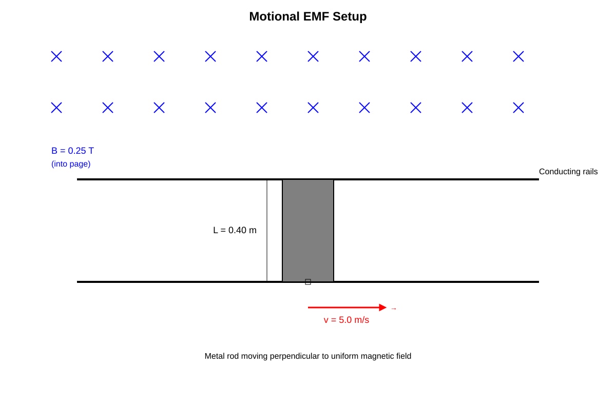
Generated diagram for Q18.
(a) Calculate the emf induced across the ends of the rod.
[2]
(b) Explain, in terms of the motion of charges in the rod, how this emf is produced.
[3]
(c) The rod is now moved at the same speed but at an angle of 60∘ to the magnetic field. Calculate the new induced emf.
[2]
19. A transformer has 1000 turns on its primary coil and 200 turns on its secondary coil. The primary coil is connected to a 240 V a.c. supply.
(a) Calculate the secondary voltage.
[2]
(b) The transformer is 90% efficient. If the primary current is 0.50 A, calculate the secondary current.
[3]
(c) Explain two sources of energy loss in a real transformer and how they can be minimised.
[3]
20. A small circular coil of 100 turns and radius 0.020 m is placed at the centre of a long solenoid of 500 turns per metre. The current in the solenoid increases uniformly from 0 to 2.0 A in 0.50 s.
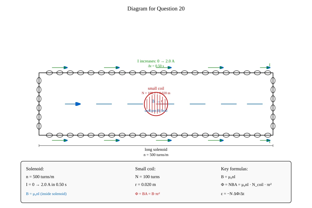
Generated diagram for Q20.
(a) Calculate the magnetic flux density inside the solenoid when the current is 2.0 A.
(Take μ0=4π×10−7 TmA−1)
[2]
(b) Calculate the magnetic flux through the small coil.
[2]
(c) Calculate the average emf induced in the small coil.
[3]
(d) State the direction of the induced current in the small coil, explaining your answer using Lenz's Law.
[2]
END OF QUIZ
Answers
A-Level Physics H2 Quiz - Electricity Magnetism
Answer Key
Section A: Electric Fields and Current Electricity
Question 1 [3 marks]
Coulomb's Law states that the magnitude of the electrostatic force between two point charges is directly proportional to the product of the magnitudes of the charges and inversely proportional to the square of the distance between them.
Mathematical expression: F=4πε01r2Q1Q2
Symbols:
- F = electrostatic force (N)
- Q1,Q2 = magnitudes of the point charges (C)
- r = distance between the charges (m)
- ε0 = permittivity of free space (8.85×10⁻¹² F m−1)
Marking: 1 mark for correct statement, 1 mark for correct equation, 1 mark for defining all symbols.
Question 2 [7 marks]
(a) [2 marks]
Using Coulomb's Law: F=4πε01r2∣Q1Q2∣
F=(0.30)2(8.99×109)×(4.0×10−6)×(6.0×10−6)
F=0.090(8.99×109)×(2.4×10−11)
F=0.0900.21576
F=2.4 N
Marking: 1 mark for correct substitution, 1 mark for correct answer.
(b) [1 mark]
The force is attractive because the charges are of opposite sign (one positive, one negative). Opposite charges attract.
(c) [4 marks]
At the midpoint, r=0.15 m from each charge.
Force on Q3 due to Q1 (repulsive, away from Q1): F1=(0.15)2(8.99×109)×(4.0×10−6)×(2.0×10−6)=0.02250.07192=3.20 N (towards Q2)
Force on Q3 due to Q2 (attractive, towards Q2): F2=(0.15)2(8.99×109)×(6.0×10−6)×(2.0×10−6)=0.02250.10788=4.79 N (towards Q2)
Both forces act in the same direction (towards Q2): Fresultant=F1+F2=3.20+4.79=7.99 N towards Q2
Marking: 1 mark for each force calculation, 1 mark for correct resultant direction and magnitude.
Question 3 [7 marks]
(a) [2 marks]
E=dV=0.040200=5000 V m−1
(b) [2 marks]
F=qE=(3.2×10−19)×5000=1.6×10⁻¹⁵ N
Direction: downward (same direction as field, since charge is positive).
(c) [3 marks]
Using conservation of energy: Work done by field=Kinetic energy gained
qV=21mv2
(3.2×10−19)×200=21×(6.6×10−26)×v2
6.4×10−17=3.3×10⁻²⁶×v2
v2=3.3×10−266.4×10−17=1.94×10⁹
v=4.4×10⁴ m s−1
Marking: 1 mark for energy equation, 1 mark for substitution, 1 mark for correct answer.
Question 4 [3 marks]
Electric potential at a point in an electric field is defined as the work done per unit positive charge in bringing a small test charge from infinity to that point.
V=qW
Difference from electric potential energy:
- Electric potential energy (U) is the total energy a charge possesses due to its position in an electric field. It depends on both the field and the charge: U=qV.
- Electric potential (V) is a property of the field itself at a point, independent of any test charge placed there. It is the potential energy per unit charge.
Marking: 1 mark for definition of potential, 1 mark for definition of potential energy, 1 mark for clear distinction.
Question 5 [9 marks]
(a) [2 marks]
The variable resistor is necessary to:
- Vary the current through the lamp and the voltage across it, allowing multiple readings to be taken.
- Limit the current to prevent damage to the lamp or components.
(b)(i) [3 marks]
Graph should show:
- Correctly labelled axes (I on y-axis, V on x-axis)
- Appropriate scale
- All 7 points plotted correctly
- A smooth curve (not a straight line) showing increasing gradient
(b)(ii) [2 marks]
At V=4.0 V, I=0.37 A:
R=IV=0.374.0=10.8 \Omega
(Alternatively, from gradient of tangent at that point: approximately 11 \Omega)
(b)(iii) [2 marks]
As voltage increases, the current increases, causing the filament to heat up. The increased temperature causes the metal ions in the filament to vibrate more, increasing the frequency of collisions between conduction electrons and the lattice. This increases the resistance of the filament.
Marking: 1 mark for temperature effect, 1 mark for explanation of resistance increase mechanism.
Section B: D.C. Circuits
Question 6 [2 marks]
Kirchhoff's First Law (Junction Rule): The algebraic sum of currents at a junction in a circuit is zero.
∑Iin=∑Iout
Physical principle: Conservation of electric charge. Charge cannot accumulate at a junction; whatever charge flows in must flow out.
Marking: 1 mark for statement, 1 mark for principle.
Question 7 [4 marks]
First, find the equivalent resistance of the parallel combination: Rparallel1=6.01+3.01=6.01+6.02=6.03
Rparallel=2.0 \Omega
Total resistance: Rtotal=R1+Rparallel=4.0+2.0=6.0 \Omega
Total current: Itotal=RtotalV=6.012.0=2.0 A
Voltage across parallel combination: Vparallel=Itotal×Rparallel=2.0×2.0=4.0 V
Current through 6.0 \Omega resistor: I6Ω=6.0Vparallel=6.04.0=0.67 A
Marking: 1 mark for parallel resistance, 1 mark for total current, 1 mark for voltage across parallel, 1 mark for final answer.
Question 8 [6 marks]
(a) [2 marks]
Total resistance: Rtotal=0.20+2.80=3.00 \Omega
Current: I=RtotalE=3.001.50=0.50 A
Terminal p.d.: V=E−Ir=1.50−(0.50×0.20)=1.50−0.10=1.40 V
(b) [2 marks]
P=I2R=(0.50)2×2.80=0.25×2.80=0.70 W
(c) [2 marks]
When external resistance decreases:
- Total current increases
- Greater voltage drop across internal resistance (Ir increases)
- Terminal p.d. (V=E−Ir) decreases
Marking: 1 mark for each correct explanation point.
Question 9 [7 marks]
(a) [2 marks]
Vout=R1+R2R2×E=3.0+6.06.0×9.0=9.06.0×9.0=6.0 V
(b) [3 marks]
Equivalent resistance of R2 and RL in parallel: Req1=6.01+12.01=12.02+12.01=12.03
Req=4.0 k\Omega
New output voltage: Vout=R1+ReqReq×E=3.0+4.04.0×9.0=7.04.0×9.0=5.14 V
(c) [2 marks]
The load resistor reduces the effective resistance of the lower part of the potential divider. This causes a greater proportion of the voltage to be dropped across R1, reducing the output voltage.
Marking: 1 mark for equivalent resistance, 1 mark for correct calculation, 1 mark for explanation.
Question 10 [6 marks]
(a) [2 marks]
Parallel combination of R2 and R3: Rparallel=4.0+4.04.0×4.0=8.016.0=2.0 \Omega
Total external resistance: Rext=R1+Rparallel=2.0+2.0=4.0 \Omega
(b) [2 marks]
Total circuit resistance: Rtotal=4.0+1.0=5.0 \Omega
I=RtotalE=5.012.0=2.4 A
(c) [2 marks]
P=I2r=(2.4)2×1.0=5.76×1.0=5.76 W
Section C: Electromagnetism
Question 11 [2 marks]
Magnetic flux density (B) is defined as the force per unit length per unit current on a straight conductor placed perpendicular to a uniform magnetic field.
B=ILF
SI unit: Tesla (T), where 1 T=1 N A−1 m−1
Marking: 1 mark for definition, 1 mark for unit.
Question 12 [6 marks]
(a) [2 marks]
F=BILsinθ=0.20×4.0×0.50×sin90∘=0.20×4.0×0.50×1=0.40 N
(b) [2 marks]
F=BILsinθ=0.20×4.0×0.50×sin30∘=0.40×0.50=0.20 N
(c) [2 marks]
The force can be increased by:
- Increasing the current in the wire
- Increasing the magnetic flux density
- Increasing the length of the wire in the field
- Orienting the wire perpendicular to the field (θ=90∘)
(Any two valid methods, 1 mark each)
Question 13 [6 marks]
(a) [2 marks]
Area of one turn: A=0.040×0.060=2.4×10⁻³ m2
Since the plane is parallel to the field, the normal to the coil is perpendicular to B: Φ=BAcosθ=0.15×(2.4×10−3)×cos90∘=0 Wb
(b) [3 marks]
τ=BANIsinθ
where θ is the angle between the normal to the coil and the field. Since the plane is parallel to B, the normal is perpendicular to B, so θ=90∘:
τ=0.15×(2.4×10−3)×50×2.0×sin90∘
τ=0.15×2.4×10−3×50×2.0×1=0.036 N m
(c) [1 mark]
If the number of turns is doubled, the torque is also doubled (since τ∝N).
Question 14 [7 marks]
(a) [2 marks]
F=qvBsinθ=(1.60×10−19)×(3.0×106)×0.050×sin90∘
F=1.60×10−19×3.0×106×0.050=2.4×10⁻¹⁴ N
(b) [3 marks]
The magnetic force provides the centripetal force for circular motion: qvB=rmv2
r=qBmv=(1.60×10−19)×0.050(9.11×10−31)×(3.0×106)
r=8.0×10−212.733×10−24=3.42×10⁻⁴ m
(c) [2 marks]
T=v2πr=3.0×1062π×3.42×10−4=3.0×1062.148×10−3=7.16×10⁻¹⁰ s
Question 15 [6 marks]
(a) [2 marks]
B=2πrμ0IP=2π×0.10(4π×10−7)×5.0=0.102.0×10−6=2.0×10⁻⁵ T
(b) [2 marks]
LF=BIQ=(2.0×10−5)×8.0=1.6×10⁻⁴ N m−1
(c) [2 marks]
The force is attractive. Parallel currents in the same direction produce attractive forces between wires. This can be verified using Fleming's Left-Hand Rule: the magnetic field from wire P at wire Q is directed into the page, and with current upward in wire Q, the force is towards wire P.
Section D: Electromagnetic Induction
Question 16 [4 marks]
Faraday's Law: The magnitude of the induced emf in a circuit is directly proportional to the rate of change of magnetic flux linkage through the circuit.
E=−dtd(NΦ)
Lenz's Law: The direction of the induced current is such that it opposes the change in magnetic flux that produced it.
Relation: The negative sign in Faraday's Law represents Lenz's Law. It indicates that the induced emf (and hence induced current) acts in a direction that opposes the change in flux linkage, ensuring conservation of energy.
Marking: 1 mark for Faraday's Law statement, 1 mark for equation, 1 mark for Lenz's Law, 1 mark for explanation of relationship.
Question 17 [6 marks]
(a) [2 marks]
Initial flux linkage (plane perpendicular to field, so θ=0∘): NΦ=NBAcosθ=200×0.30×0.020×cos0∘=200×0.30×0.020×1=1.2 Wb
(b) [3 marks]
Final flux linkage (plane parallel to field, so θ=90∘): NΦfinal=NBAcos90∘=0
Average emf: E=−ΔtΔ(NΦ)=−0.100−1.2=0.101.2=12 V
(c) [1 mark]
If the rotation is carried out more slowly, the rate of change of flux linkage is smaller, so the induced emf would be smaller (since E∝dtdΦ).
Question 18 [7 marks]
(a) [2 marks]
E=BLv=0.25×0.40×5.0=0.50 V
(b) [3 marks]
As the rod moves through the magnetic field, the free electrons in the rod also move with velocity v. These moving charges experience a magnetic force F=qvB (Fleming's Left-Hand Rule). The force on positive charges is in one direction, causing a separation of charges. This creates an electric field within the rod. Equilibrium is reached when the electric force equals the magnetic force, resulting in a potential difference (emf) across the ends of the rod.
(c) [2 marks]
E=BLvsinθ=0.25×0.40×5.0×sin60∘=0.50×0.866=0.43 V
Question 19 [8 marks]
(a) [2 marks]
VPVS=NPNS
VS=VP×NPNS=240×1000200=240×0.20=48 V
(b) [3 marks]
Input power: Pin=VPIP=240×0.50=120 W
Output power: Pout=η×Pin=0.90×120=108 W
IS=VSPout=48108=2.25 A
(c) [3 marks]
Sources of energy loss:
-
Copper losses (I2R losses): Resistance of the windings causes heating. Minimised by using thick copper wire with low resistance.
-
Eddy current losses: Changing magnetic flux induces eddy currents in the core, causing heating. Minimised by using a laminated core (thin insulated sheets).
-
Hysteresis losses: Repeated magnetisation and demagnetisation of the core causes energy loss. Minimised by using soft magnetic materials (e.g., soft iron) with low hysteresis.
(Any two sources with minimisation methods, 1.5 marks each)
Question 20 [9 marks]
(a) [2 marks]
B=μ0nI=(4π×10−7)×500×2.0=4π×10−7×1000=1.26×10⁻³ T
(b) [2 marks]
Area of small coil: A=πr2=π×(0.020)2=1.257×10⁻³ m2
Φ=BA=(1.26×10−3)×(1.257×10−3)=1.58×10⁻⁶ Wb
(c) [3 marks]
Initial flux linkage: NΦinitial=0 (since I=0)
Final flux linkage: NΦfinal=100×1.58×10−6=1.58×10⁻⁴ Wb
E=−ΔtΔ(NΦ)=−0.501.58×10−4−0=3.16×10⁻⁴ V
(d) [2 marks]
The current in the solenoid is increasing, so the magnetic flux through the small coil is increasing. By Lenz's Law, the induced current in the small coil will flow in a direction that opposes this increase. Therefore, the induced current will create a magnetic field in the opposite direction to the solenoid's field. Using the right-hand grip rule, the induced current flows in the opposite direction to the solenoid current.
END OF ANSWER KEY
Free quiz and exam paper access
Enter your details to view this paper
Your access is remembered on this device.