From Real Exams Quiz
A Level H1 Physics Electricity Magnetism Quiz
Free A Level H1 Physics Electricity Magnetism quiz, LongCat Exam version, with questions, answers, and A Level-style practice for Singapore students.
These static practice materials are generated from the site's syllabus and paper-generation workflow, with source and model context shown so students and parents can evaluate the material before use.
Questions
A-Level Physics H1 Quiz - Electricity Magnetism
Name: ___________________________
Class: ___________________________
Date: ___________________________
Score: ________ / 50
Duration: 60 minutes
Total Marks: 50
Instructions:
- Answer ALL questions.
- Show all working clearly. Marks are awarded for correct method even if the final answer is incorrect.
- Include units in your final answers where appropriate.
- The number of marks for each question or part-question is shown in brackets [ ].
- You may use a calculator.
Section A: Short Answer Questions (1–5)
1. Define electric current. State its SI unit.
[2]
2. State Ohm's law.
[1]
3. A wire has a resistance of 8.0 Ω. When a potential difference of 12 V is applied across it, calculate the current flowing through the wire.
Working:
[2]
4. Define electromotive force (e.m.f.) of a cell.
[2]
5. State Kirchhoff's first law (junction rule).
[1]
Section B: Structured Questions (6–15)
6. A cell of e.m.f. 1.5 V and internal resistance 0.50 Ω is connected to a resistor of 2.5 Ω.
(a) Calculate the total resistance of the circuit.
[1]
(b) Calculate the current in the circuit.
[2]
(c) Calculate the terminal potential difference across the cell.
[2]
7. Two resistors, R₁ = 6.0 Ω and R₂ = 3.0 Ω, are connected in parallel across a battery of negligible internal resistance. The current through R₁ is 0.50 A.
(a) Calculate the potential difference across R₁.
[1]
(b) State the potential difference across R₂. Explain your answer.
[1]
(c) Calculate the current through R₂.
[2]
8. The resistivity of copper at room temperature is 1.7×10⁻⁸ Ω m. A copper wire has length 2.0 m and cross-sectional area 3.0×10⁻⁷ m².
(a) Calculate the resistance of the wire.
[2]
(b) The wire is now stretched to twice its original length while keeping the volume constant. Without calculation, state and explain how the resistance changes.
[2]
9. A potential divider circuit is set up as shown below.
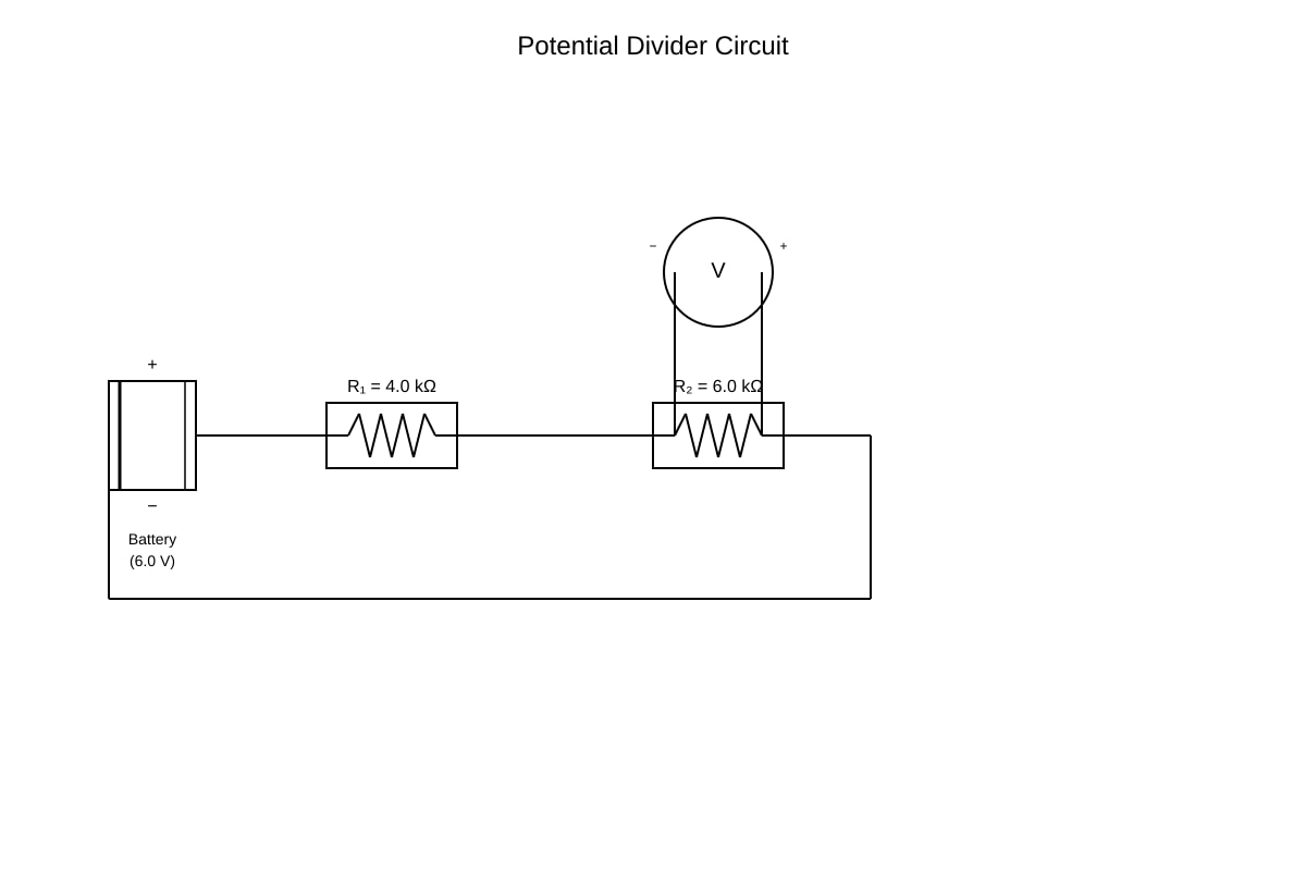
Generated experimental_setup for Q9.
(a) Calculate the total resistance of the circuit.
[1]
(b) Calculate the current through the circuit.
[2]
(c) Calculate the output potential difference across R₂.
[2]
(d) The 6.0 kΩ resistor is replaced with a 12.0 kΩ resistor. State and explain what happens to the output potential difference.
[2]
10. A battery of e.m.f. 9.0 V and internal resistance r is connected to a variable external resistor R. When R = 2.0 Ω, the current in the circuit is 1.5 A.
(a) Use the data to calculate the internal resistance r of the battery.
[3]
(b) Calculate the power dissipated in the external resistor when R = 2.0 Ω.
[2]
(c) Explain why the terminal p.d. is less than the e.m.f. of the battery.
[2]
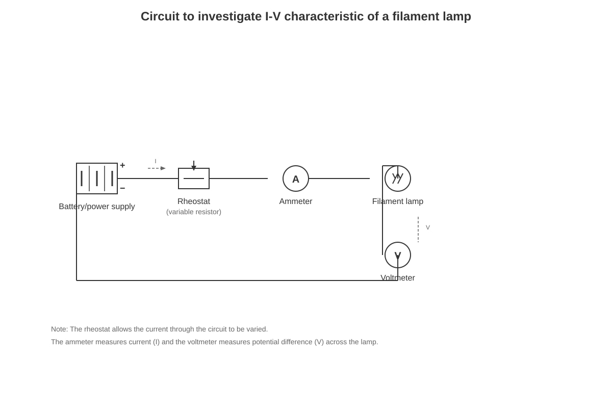
11. A student sets up the following circuit to investigate the I–V characteristic of a filament lamp.
Generated experimental_setup for Q11.
The student obtains the following data:
| Potential Difference / V | Current / A |
|---|---|
| 0.0 | 0.00 |
| 1.0 | 0.20 |
| 2.0 | 0.35 |
| 3.0 | 0.48 |
| 4.0 | 0.58 |
| 5.0 | 0.66 |
| 6.0 | 0.72 |
(a) On the axes provided, sketch the I–V characteristic for the filament lamp.
[2]
(b) Explain why the graph is not a straight line.
[2]
(c) Calculate the resistance of the filament lamp at 3.0 V.
[2]
12. A cell of e.m.f. 2.0 V and internal resistance 0.80 Ω is connected in series with a resistor of 3.2 Ω.
(a) Show that the current in the circuit is 0.50 A.
[2]
(b) Calculate the power delivered by the cell.
[2]
(c) Calculate the power dissipated in the internal resistance.
[2]
(d) Hence calculate the efficiency of the cell (the fraction of total power delivered to the external resistor).
[2]
13. Three resistors are connected as shown: R₁ = 2.0 Ω and R₂ = 3.0 Ω are in series, and this combination is in parallel with R₃ = 5.0 Ω. The circuit is connected to a 10.0 V battery of negligible internal resistance.
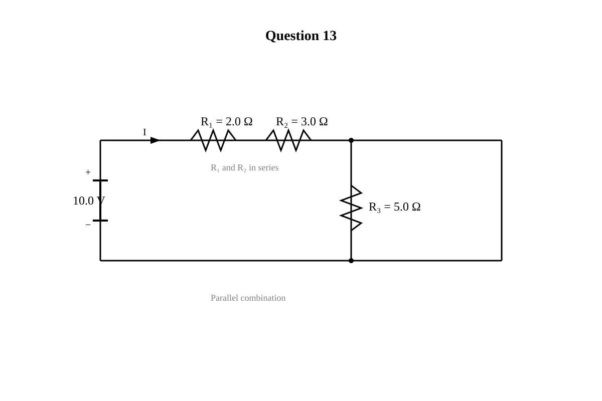
Generated diagram for Q13.
(a) Calculate the equivalent resistance of R₁ and R₂ in series.
[1]
(b) Calculate the total equivalent resistance of the circuit.
[2]
(c) Calculate the total current drawn from the battery.
[2]
(d) Calculate the current through R₃.
[2]
14. A wire of length 5.0 m and cross-sectional area 2.0×10⁻⁶ m² has a resistance of 0.040 Ω.
(a) Calculate the resistivity of the material of the wire.
[3]
(b) The wire is replaced with another wire of the same material but with twice the length and half the cross-sectional area. Calculate the new resistance.
[3]
15. A battery is connected to two resistors in parallel: R₁ = 4.0 Ω and R₂ = 12.0 Ω. The e.m.f. of the battery is 6.0 V and its internal resistance is 0.50 Ω.
(a) Calculate the equivalent resistance of the two parallel resistors.
[2]
(b) Calculate the total current from the battery.
[2]
(c) Calculate the terminal p.d. of the battery.
[2]
(d) Calculate the current through R₁.
[2]
Section C: Application and Data Interpretation (16–20)
16. A student investigates how the resistance of a thermistor changes with temperature. The results are shown below:
| Temperature / °C | Resistance / kΩ |
|---|---|
| 10 | 25.0 |
| 20 | 12.5 |
| 30 | 6.5 |
| 40 | 3.5 |
| 50 | 2.0 |
| 60 | 1.2 |
(a) Describe the relationship between temperature and resistance of the thermistor.
[2]
(b) The thermistor is connected in series with a 5.0 kΩ fixed resistor and a 6.0 V battery of negligible internal resistance. At a temperature of 30 °C, calculate the total resistance of the circuit.
[1]
(c) Calculate the current in the circuit at 30 °C.
[2]
(d) Calculate the potential difference across the fixed resistor at 30 °C.
[2]
(e) Explain, without further calculation, what happens to the potential difference across the fixed resistor as the temperature increases.
[2]
17. A car battery has an e.m.f. of 12.0 V and an internal resistance of 0.050 Ω. When starting the car, the starter motor draws a current of 100 A.
(a) Calculate the terminal p.d. of the battery when the starter motor is operating.
[2]
(b) Calculate the power delivered to the starter motor.
[2]
(c) Calculate the power wasted as heat inside the battery.
[2]
(d) Explain why car headlights may dim when the starter motor is engaged.
[2]
18. A circuit consists of a cell of e.m.f. 6.0 V and internal resistance 1.0 Ω connected to two resistors in series: R₁ = 3.0 Ω and R₂ = 6.0 Ω.
(a) Calculate the current in the circuit.
[2]
(b) Calculate the power dissipated in R₂.
[2]
(c) Calculate the total power supplied by the cell.
[2]
(d) Show that the total power supplied equals the sum of the power dissipated in all three resistances (R₁, R₂, and r).
[3]
19. A student uses a potentiometer to compare the e.m.f. of two cells. The potentiometer wire has uniform cross-section and length 100 cm.
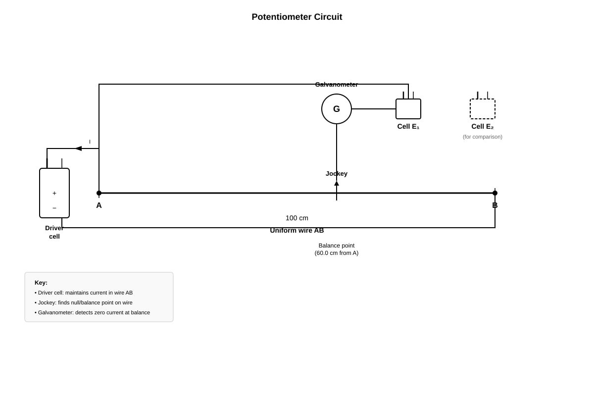
Generated experimental_setup for Q19.
For cell E₁, the balance point is found at 60.0 cm from end A. For cell E₂, the balance point is at 45.0 cm from end A.
(a) Explain why no current flows through the galvanometer at the balance point.
[2]
(b) If E₁ has an e.m.f. of 1.50 V, calculate the e.m.f. of E₂.
[3]
(c) State one advantage of using a potentiometer rather than a voltmeter to measure e.m.f.
[1]
20. A household circuit has a 240 V supply. A heater of resistance 48 Ω and a lamp of resistance 96 Ω are connected in parallel to the supply.
(a) Calculate the current through the heater.
[1]
(b) Calculate the current through the lamp.
[1]
(c) Calculate the total current drawn from the supply.
[2]
(d) Calculate the total power consumed by both appliances.
[2]
(e) The heater and lamp are now connected in series instead of parallel across the same 2.0 V supply. Without detailed calculation, explain whether the total power consumed will be greater or less than in the parallel case.
[2]
Answers
A-Level Physics H1 Quiz - Electricity Magnetism
Answer Key
Question 1 [2 marks]
Answer: Electric current is the rate of flow of electric charge through a point in a circuit. The SI unit is the ampere (A).
Marking:
- [B1] Rate of flow of charge (or equivalent wording)
- [B1] Ampere (A)
Teaching notes: Current is defined as I=tQ, where Q is charge in coulombs and t is time in seconds. One ampere equals one coulomb per second. Students sometimes confuse current with voltage — current is the flow, voltage is the driving force.
Question 2 [1 mark]
Answer: Ohm's law states that the current flowing through a conductor is directly proportional to the potential difference across it, provided the temperature (and other physical conditions) remain constant.
Marking:
- [B1] Current is directly proportional to p.d. (with constant temperature condition)
Teaching notes: Mathematically: V=IR. The key qualifier is "provided temperature remains constant" — this is essential because resistance changes with temperature for most conductors.
Question 3 [2 marks]
Answer:
Using Ohm's law: V=IR
I=RV=8.012=1.5 A
Marking:
- [B1] Correct formula or substitution
- [B1] Correct answer: 1.5 A
Teaching notes: This is a direct application of Ohm's law. Students should always write the formula, substitute values, then give the answer with units. Common error: forgetting to include the unit (A).
Question 4 [2 marks]
Answer: The electromotive force (e.m.f.) of a cell is the total energy per unit charge supplied by the cell (or the work done per unit charge in moving charge around a complete circuit). It is measured in volts (V).
Marking:
- [B1] Energy per unit charge (or work done per unit charge) supplied by the cell
- [B1] Volts (V)
Teaching notes: E.m.f. represents the total energy converted from chemical (or other) form to electrical energy per coulomb of charge. It is NOT a force despite the name. ε=QW.
Question 5 [1 mark]
Answer: Kirchhoff's first law states that the total current entering a junction equals the total current leaving the junction. (This is a consequence of conservation of charge.)
Marking:
- [B1] Total current in = total current out (or equivalent, with mention of junction)
Teaching notes: ∑Iin=∑Iout. This law reflects conservation of electric charge — charge cannot accumulate at a junction.
Question 6 [5 marks]
(a) [1 mark]
Total resistance: Rtotal=R+r=2.5+0.50=3.0 Ω
Answer: 3.0 Ω
(b) [2 marks]
Using ε=I(R+r):
I=R+rε=3.01.5=0.50 A
Marking:
- [B1] Correct formula/substitution
- [B1] Correct answer: 0.50 A
(c) [2 marks]
Terminal p.d.: V=IR=0.50×2.5=1.25 V
Or: V=ε−Ir=1.5−(0.50×0.50)=1.5−0.25=1.25 V
Marking:
- [B1] Correct method
- [B1] Correct answer: 1.25 V
Teaching notes: The terminal p.d. is the voltage available to the external circuit. It is less than the e.m.f. because some energy is used to push current through the internal resistance. The "lost volts" = Ir=0.25 V.
Question 7 [4 marks]
(a) [1 mark]
V=IR1=0.50×6.0=3.0 V
Answer: 3.0 V
(b) [1 mark]
The potential difference across R₂ is also 3.0 V because components connected in parallel have the same potential difference across them.
(c) [2 marks]
I2=R2V=3.03.0=1.0 A
Marking:
- [B1] Correct formula/substitution
- [B1] Correct answer: 1.0 A
Teaching notes: In parallel, the voltage across each branch is the same. The current divides inversely with resistance — the smaller resistor carries the larger current.
Question 8 [4 marks]
(a) [2 marks]
Using R=AρL:
R=3.0×10−71.7×10−8×2.0=3.0×10−73.4×10−8=0.113 Ω ≈ 0.11 Ω
Marking:
- [B1] Correct formula and substitution
- [B1] Correct answer: 0.11 Ω (or 0.113 Ω)
(b) [2 marks]
When the wire is stretched to twice its length, volume stays constant, so the cross-sectional area halves.
Since R=AρL: doubling L doubles R, and halving A also doubles R. Combined effect: R increases by a factor of 4.
Marking:
- [B1] Resistance increases by factor of 4 (or equivalent)
- [B1] Correct explanation referencing R=ρL/A and area halving
Teaching notes: Volume = A×L = constant. If L doubles, A must halve. So Rnew=A/2ρ(2L)=4×AρL=4R.
Question 9 [7 marks]
(a) [1 mark]
Rtotal=R1+R2=4.0+6.0=10.0 kΩ
Answer: 10.0 kΩ
(b) [2 marks]
I=RtotalV=10.0×1036.0=6.0×10⁻⁴ A = 0.60 mA
Marking:
- [B1] Correct substitution
- [B1] Correct answer: 0.60 mA (or 6.0×10⁻⁴ A)
(c) [2 marks]
Vout=IR2=6.0×10−4×6.0×103=3.6 V
Or using potential divider: Vout=R1+R2R2×ε=10.06.0×6.0=3.6 V
Marking:
- [B1] Correct method
- [B1] Correct answer: 3.6 V
(d) [2 marks]
The output p.d. increases. Since Vout=R1+R2R2×ε, increasing R2 increases the fraction of the total voltage dropped across R2.
New Vout=4.0+12.012.0×6.0=16.012.0×6.0=4.5 V
Marking:
- [B1] Output p.d. increases
- [B1] Correct explanation (larger share of total resistance → larger share of voltage)
Teaching notes: The potential divider equation Vout=R1+R2R2×Vin is fundamental. Increasing the resistance across which you measure the output increases the output voltage.
Question 10 [7 marks]
(a) [3 marks]
Using ε=I(R+r):
9.0=1.5×(2.0+r)
2.0+r=1.59.0=6.0
r=6.0−2.0=4.0 Ω
Marking:
- [B1] Correct formula ε=I(R+r)
- [B1] Correct substitution
- [B1] Correct answer: 4.0 Ω
(b) [2 marks]
P=I2R=(1.5)2×2.0=2.25×2.0=4.5 W
Marking:
- [B1] Correct formula/substitution
- [B1] Correct answer: 4.5 W
(c) [2 marks]
The terminal p.d. is less than the e.m.f. because some energy is used to drive current through the internal resistance of the battery. There is a "lost voltage" (Ir) across the internal resistance, so Vterminal=ε−Ir.
Marking:
- [B1] Energy is dissipated in the internal resistance / lost volts exist
- [B1] Terminal p.d. = e.m.f. − lost volts (or V=ε−Ir)
Teaching notes: This is a common exam question. The internal resistance acts like a small resistor inside the battery, consuming some of the energy. The larger the current, the greater the lost volts.
Question 11 [6 marks]
(a) [2 marks]
The I–V graph should be a curve starting at the origin, rising steeply at first and then flattening off (concave down / decreasing gradient). It passes through or near all the data points.
Marking:
- [B1] Correct shape — curve through origin, not a straight line
- [B1] Correct general trend — gradient decreases as V increases
Expected visual features for image_placeholder Q11-fig1: The circuit diagram should show a battery, rheostat (variable resistor), ammeter in series with the filament lamp, and voltmeter in parallel across the lamp. The rheostat allows the student to vary the voltage across the lamp from zero upwards.
(b) [2 marks]
As the potential difference increases, the current increases, which causes the filament to heat up. The resistance of the filament increases with temperature (because the metal ions vibrate more, causing more frequent collisions with conduction electrons). Since R=V/I increases, the gradient of the graph (I/V) decreases.
Marking:
- [B1] Filament heats up / temperature increases
- [B1] Resistance increases with temperature (or more electron-ion collisions)
(c) [2 marks]
At V=3.0 V, I=0.48 A:
R=IV=0.483.0=6.25 Ω ≈ 6.3 Ω
Marking:
- [B1] Correct reading from table (0.48 A at 3.0 V)
- [B1] Correct answer: 6.3 Ω (or 6.25 Ω)
Teaching notes: Note that this is the resistance at that specific operating point. The filament is ohmic only instantaneously — the resistance changes as the filament heats up. This is why the graph is curved.
Question 12 [8 marks]
(a) [2 marks]
Total resistance = 3.2+0.80=4.0 Ω
I=Rtotalε=4.02.0=0.50 A ✓
Marking:
- [B1] Correct total resistance
- [B1] Correct current: 0.50 A
(b) [2 marks]
Ptotal=εI=2.0×0.50=1.0 W
Marking:
- [B1] Correct formula
- [B1] Correct answer: 1.0 W
(c) [2 marks]
Pr=I2r=(0.50)2×0.80=0.25×0.80=0.20 W
Marking:
- [B1] Correct formula
- [B1] Correct answer: 0.20 W
(d) [2 marks]
Power to external resistor: PR=I2R=(0.50)2×3.2=0.80 W
Efficiency = PtotalPR=1.00.80=0.80 = 80%
Marking:
- [B1] Correct power to external resistor (0.80 W)
- [B1] Correct efficiency: 80% (or 0.80)
Teaching notes: Efficiency = R+rR×100%. Maximum power transfer occurs when R=r, but efficiency is only 50% at that point. For high efficiency, R should be much larger than r.
Question 13 [7 marks]
(a) [1 mark]
Rseries=R1+R2=2.0+3.0=5.0 Ω
Answer: 5.0 Ω
(b) [2 marks]
The 5.0 Ω (series combination) is in parallel with R3=5.0 Ω:
Req1=5.01+5.01=5.02
Req=2.5 Ω
Marking:
- [B1] Correct parallel formula
- [B1] Correct answer: 2.5 Ω
(c) [2 marks]
Itotal=ReqV=2.510.0=4.0 A
Marking:
- [B1] Correct substitution
- [B1] Correct answer: 4.0 A
(d) [2 marks]
The p.d. across the parallel combination:
Vparallel=Itotal×Req=4.0×2.5=10.0 V
(This makes sense — the full battery voltage appears across the parallel combination.)
Current through R3: I3=R3V=5.010.0=2.0 A
Marking:
- [B1] Correct p.d. across parallel branch (10.0 V)
- [B1] Correct answer: 2.0 A
Teaching notes: In a parallel circuit with two equal resistances, the current splits equally. Since total current is 4.0 A, each branch carries 2.0 A.
Question 14 [6 marks]
(a) [3 marks]
Using R=AρL, rearranging: ρ=LRA
ρ=5.00.040×2.0×10−6=5.08.0×10−8=1.6×10⁻⁸ Ω m
Marking:
- [B1] Correct rearrangement of formula
- [B1] Correct substitution
- [B1] Correct answer: 1.6×10⁻⁸ Ω m
(b) [3 marks]
New length: L′=2×5.0=10.0 m
New area: A′=21×2.0×10−6=1.0×10⁻⁶ m²
R′=A′ρL′=1.0×10−61.6×10−8×10.0=1.0×10−61.6×10−7=0.16 Ω
Alternatively: doubling L doubles R; halving A doubles R again. So R increases by factor of 4: R′=4×0.040=0.16 Ω
Marking:
- [B1] Correct new length and area
- [B1] Correct formula/substitution
- [B1] Correct answer: 0.16 Ω
Teaching notes: Resistivity ρ is a material property and does not change when the dimensions of the wire change. Only resistance R changes with dimensions.
Question 15 [8 marks]
(a) [2 marks]
Req1=4.01+12.01=12.03+12.01=12.04=3.01
Req=3.0 Ω
Marking:
- [B1] Correct formula
- [B1] Correct answer: 3.0 Ω
(b) [2 marks]
Total resistance including internal resistance: Rtotal=3.0+0.50=3.5 Ω
I=Rtotalε=3.56.0=1.71 A ≈ 1.7 A
Marking:
- [B1] Correct total resistance
- [B1] Correct answer: 1.7 A (or 1.71 A or 712 A)
(c) [2 marks]
Terminal p.d.: V=IReq=1.71×3.0=5.14 V ≈ 5.1 V
Or: V=ε−Ir=6.0−(1.71×0.50)=6.0−0.857=5.14 V
Marking:
- [B1] Correct method
- [B1] Correct answer: 5.1 V (or 5.14 V)
(d) [2 marks]
The p.d. across the parallel combination is the terminal p.d. = 5.14 V.
Current through R1: I1=R1V=4.05.14=1.29 A ≈ 1.3 A
Marking:
- [B1] Correct use of terminal p.d.
- [B1] Correct answer: 1.3 A (or 1.29 A)
Teaching notes: In parallel, the smaller resistor carries the larger current. Check: I1×R1=I2×R2=Vterminal.
Question 16 [9 marks]
(a) [2 marks]
As the temperature increases, the resistance of the thermistor decreases. The relationship is non-linear — the resistance decreases rapidly at first and then more slowly (or the decrease is approximately exponential).
Marking:
- [B1] Resistance decreases with increasing temperature
- [B1] Non-linear / exponential decrease (or equivalent description)
(b) [1 mark]
At 30 °C, thermistor resistance = 6.5 kΩ
Total resistance = 6.5+5.0=11.5 kΩ
Answer: 11.5 kΩ
(c) [2 marks]
I=RtotalV=11.5×1036.0=5.22×10⁻⁴ A ≈ 0.52 mA
Marking:
- [B1] Correct substitution
- [B1] Correct answer: 0.52 mA
(d) [2 marks]
Vfixed=IRfixed=5.22×10−4×5.0×103=2.61 V ≈ 2.6 V
Marking:
- [B1] Correct method
- [B1] Correct answer: 2.6 V
(e) [2 marks]
As temperature increases, the thermistor resistance decreases, so the total resistance decreases and the current increases. Since the fixed resistor has constant resistance, V=IR across it increases as current increases.
Marking:
- [B1] Thermistor resistance decreases → current increases
- [B1] p.d. across fixed resistor increases (since V=IR and I increases)
Teaching notes: This is a practical application of a potential divider. The thermistor acts as a temperature sensor — as temperature rises, more voltage appears across the fixed resistor, which can be used to trigger a circuit.
Question 17 [8 marks]
(a) [2 marks]
V=ε−Ir=12.0−(100×0.050)=12.0−5.0=7.0 V
Marking:
- [B1] Correct formula
- [B1] Correct answer: 7.0 V
(b) [2 marks]
P=VI=7.0×100=700 W
Marking:
- [B1] Correct formula
- [B1] Correct answer: 700 W
(c) [2 marks]
Pwasted=I2r=(100)2×0.050=10000×0.050=500 W
Marking:
- [B1] Correct formula
- [B1] Correct answer: 500 W
(d) [2 marks]
When the starter motor is engaged, a very large current flows. This causes a large voltage drop across the internal resistance of the battery (Ir), reducing the terminal p.d. available to the rest of the circuit. Since the headlights are connected to the same supply, the reduced terminal p.d. means less current flows through the headlights, so they dim.
Marking:
- [B1] Large current causes large lost volts / reduced terminal p.d.
- [B1] Reduced p.d. across headlights → less current → dimmer
Teaching notes: This is a real-world application of internal resistance. The total power supplied is 1200 W, of which 500 W is wasted internally — an efficiency of only 58%.
Question 18 [9 marks]
(a) [2 marks]
Total resistance = 1.0+3.0+6.0=10.0 Ω
I=Rtotalε=10.06.0=0.60 A
Marking:
- [B1] Correct total resistance
- [B1] Correct answer: 0.60 A
(b) [2 marks]
PR2=I2R2=(0.60)2×6.0=0.36×6.0=2.16 W ≈ 2.2 W
Marking:
- [B1] Correct formula
- [B1] Correct answer: 2.2 W (or 2.16 W)
(c) [2 marks]
Ptotal=εI=6.0×0.60=3.6 W
Marking:
- [B1] Correct formula
- [B1] Correct answer: 3.6 W
(d) [3 marks]
Power in R1: P1=I2R1=(0.60)2×3.0=1.08 W
Power in R2: P2=2.16 W (from part b)
Power in r: Pr=I2r=(0.60)2×1.0=0.36 W
Sum: P1+P2+Pr=1.08+2.16+0.36=3.60 W = Ptotal ✓
Marking:
- [B1] Correct power in R1
- [B1] Correct power in r
- [B1] Sum equals total power (3.6 W)
Teaching notes: This demonstrates conservation of energy in a circuit. The total power supplied by the cell equals the total power dissipated in all resistances. This is a common exam verification question.
Question 19 [6 marks]
(a) [2 marks]
At the balance point, the e.m.f. of the cell being tested exactly equals the potential difference across the length of potentiometer wire from the end to the jockey. Since there is no potential difference between the cell and that section of wire, no current flows through the galvanometer.
Marking:
- [B1] E.m.f. of cell equals p.d. across the wire length
- [B1] No potential difference → no current (or null deflection)
Expected visual features for image_placeholder Q19-fig1: The potentiometer circuit should show a driver cell connected across a uniform wire AB of length 100 cm. A jockey can make contact at any point along the wire. A galvanometer connects the jockey to the positive terminal of the cell under test (E₁), with the negative terminal of the cell connected to end A of the wire.
(b) [3 marks]
For a potentiometer with uniform wire, the e.m.f. is proportional to the balance length:
E1E2=L1L2
E2=E1×L1L2=1.50×60.045.0=1.50×0.75=1.125 V ≈ 1.13 V
Marking:
- [B1] Correct proportionality relationship
- [B1] Correct substitution
- [B1] Correct answer: 1.13 V (or 1.125 V)
(c) [1 mark]
At the balance point, no current is drawn from the cell being measured, so the e.m.f. is measured accurately without any error due to the internal resistance of the cell. (A voltmeter draws some current, causing a systematic error.)
Marking:
- [B1] No current drawn from cell / measures true e.m.f. / no internal resistance error
Teaching notes: The potentiometer is a null method — it compares voltages without drawing current from the unknown source. This makes it more accurate than a voltmeter for measuring e.m.f.
Question 20 [8 marks]
(a) [1 mark]
Iheater=RV=48240=5.0 A
Answer: 5.0 A
(b) [1 mark]
Ilamp=RV=96240=2.5 A
Answer: 2.5 A
(c) [2 marks]
In parallel, total current = sum of branch currents:
Itotal=5.0+2.5=7.5 A
Marking:
- [B1] Correct method (adding currents)
- [B1] Correct answer: 7.5 A
(d) [2 marks]
Ptotal=Pheater+Plamp=RheaterV2+RlampV2
=482402+962402=4857600+9657600=1200+600=1800 W
Marking:
- [B1] Correct method
- [B1] Correct answer: 1800 W (or 1.8 kW)
(e) [2 marks]
In series, the total resistance increases (Rtotal=48+96=144 Ω compared to the parallel equivalent of 32 Ω). Since P=RV2, a larger total resistance means less total power consumed.
Marking:
- [B1] Total resistance increases in series
- [B1] Power decreases (since P=V2/R and R increases)
Teaching notes: In parallel, each appliance gets the full supply voltage, so each operates at its rated power. In series, the voltage is shared, so each appliance receives less than the full voltage and operates at reduced power. This is why household appliances are connected in parallel.
Free quiz and exam paper access
Enter your details to view this paper
Your access is remembered on this device.